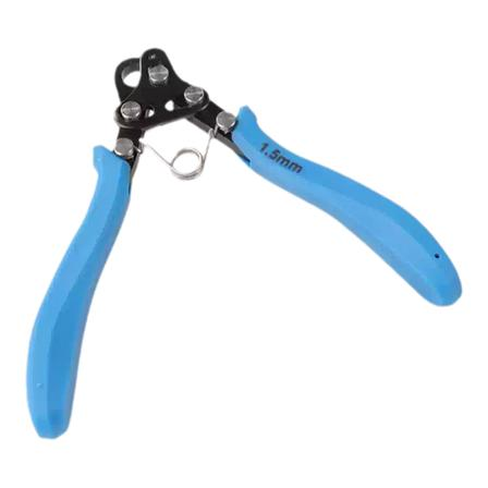
9 字钳(九字卷针钳)
9字钳是木质帆船模型金属舾装制作的专用塑形工具,核心用于标准化加工9字钉、金属丝圆环与挂环,解决手工用尖嘴钳弯折时圈径不一、圆度差、效率低的问题,可批量制作尺寸统一的系缆配件与索具连接件,是提升舾装细节规整度的必备工具。
---
结构与工作原理
钳头内置固定直径的圆柱绕线柱与卡位槽,夹紧金属丝后通过转动钳身即可一次性绕出标准正圆,无需手工反复校准圆度;主流分为单规格固定圈径款和六段阶梯多槽款,前者精度更高,后者可一把覆盖多种圈径需求。
船模场景核心用途
1. 9字钉标准化加工
批量制作黄铜9字钉,弯钩大小、圆度完全一致,安装在甲板、舷墙作为系缆挂点时,整体外观规整统一,远优于手工弯折的参差效果。
2. 金属丝圆圈制作
加工索具挂环、滑轮吊环、锚链链环、铜栏杆收尾圈等环形零件,尺寸精度高,装配后索具、栏杆的受力与形态更稳定。
3. 金属件细节修饰
修整歪斜的金属圈、调整9字钉弯钩角度、收口开口环,快速修正手工弯折的瑕疵,提升金属舾装件的完成度。
选型建议(对应船模比例)
1:96 ~ 1:150 小比例模型;推荐圈径规格:1.5mm;适配铜丝线径:0.4 ~ 0.6mm。
1:50 ~ 1:80 主流中比例模型;推荐圈径规格:2.0 ~ 2.5mm;适配铜丝线径:0.6 ~ 0.8mm(最常用)。
1:20 ~ 1:48 大比例模型;推荐圈径规格:3.0mm;适配铜丝线径:0.8 ~ 1.2mm。
> 进阶制作可选择六段阶梯圆嘴款,一把钳覆盖多档圈径,适配全比例船模的各类金属丝加工需求。
标准操作与注意事项
1. 操作流程:先将黄铜丝剪至定长,一端弯折小幅直角;将铜丝卡入钳头卡槽,绕线柱顶住弯折处并夹紧;匀速转动钳身绕满一整圈;最后修整直杆角度,保证9字钉直杆与圆环垂直。
2. 材质限制:仅适配铜、铝等软质金属丝,禁止弯折高强度钢丝,避免损伤绕线柱、导致圆度失准。
3. 精度保护:绕线柱为精度核心部件,避免磕碰、摔砸,否则绕出的圆圈会出现椭圆、尺寸偏差。
4. 线径匹配:铜丝线径需与圈径规格匹配,过粗线材强行弯折会导致钳头变形、寿命缩短。
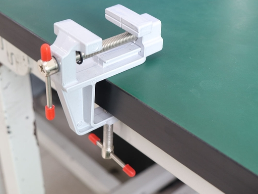
桌口钳(迷你桌虎钳)
桌口钳是木质帆船模型制作中用于工件固定的核心辅助夹具,通过C型夹持结构固定在桌面边缘,可稳定夹紧各类零件,完全解放双手,解决手持作业时工件晃动、发力不稳、对位偏差的问题,是锉削修型、钻孔、粘接固化、金属弯折等工序的标配工具。
---
结构与核心特点
船模常用款为迷你免打孔型,整体体积小巧,不占用过多操作空间,适配绝大多数模型制作桌面:
- 固定结构:底部C型夹座,通过旋钮拧紧即可固定在桌沿,无需打孔破坏桌面,适配厚度2~5cm的常规工作台。
- 可调钳口:通过丝杆调节开合宽度,常规迷你款夹持行程0~5cm,可覆盖船模绝大多数木料、金属件尺寸。
- 旋转底座:中高端款带360°旋转功能,可任意调整工件角度,适配不同方向的锉削、钻孔操作。
- 防护配件:标配软胶/软木钳口套,垫在钳口与工件之间,避免夹伤木质表面、漆面零件与光亮金属件。
---
船模场景核心用途
1. 锉削修型固定
将龙骨、肋骨、桅杆木方、金属舾装件等夹紧固定,配合锉刀进行端面找平、豁口修整、轮廓修型,全程无需手持,发力均匀稳定,修型精度远高于手持操作,也避免锉刀打滑伤手。
2. 钻孔作业固定
夹紧薄甲板、船壳板、细小舾装零件,配合手捻钻进行索具孔、定位孔加工,工件完全不位移,彻底解决薄件钻孔时打滑、跑偏、崩边的问题,尤其适合批量打孔作业。
3. 粘接组装固化
拼接龙骨与肋骨、桅杆分段、厚木方等受力构件时,涂胶后用桌口钳夹紧对齐,保持压力直至胶水完全固化,无需手工持续扶握,拼接面贴合更紧密,粘接强度更均匀。
4. 金属件加工辅助
固定铜棒、铜丝、金属栏杆底座等工件,配合尖嘴钳弯折塑形、桃口钳定长裁切,发力更稳,弯折角度、裁切长度的精度更高,适合批量制作九字钉、栏杆立柱、系缆桩等金属小零件。
5. 精细打磨辅助
夹紧微型装饰件、炮窗、小滑轮等不便手持的零件,进行边角精细打磨与抛光,避免手指直接接触打磨面,保证打磨角度一致,也防止磨伤手指。
---
选型与使用注意事项
选型要点:
1. 优先选C型夹免打孔款,安装拆卸灵活,无需破坏桌面,完全满足船模制作需求。
2. 钳口宽度选5~8cm的迷你款即可,过大过重反而占用操作空间,船模零件尺寸均适配。
3. 建议选配带软胶钳口套的款式,或自行裁剪薄木片、美纹纸做防护,避免夹伤木料表面。
使用规范
1. 夹持力度可控:木质零件、薄木片、漆面件以“夹稳不晃”为准,禁止过度拧紧,极易夹出凹痕甚至撑裂木料;金属硬构件可适当加大夹持力。
2. 表面必须防护:所有外露外观面、已上漆构件夹持时,必须垫软木片或软胶套,防止钳口齿纹压出不可逆痕迹。
3. 安装务必稳固:夹座需完全贴紧桌沿并拧紧锁死,避免锉削、发力时钳体移位,导致零件加工报废。
4. 受力方向合理:锉削、钻孔的发力方向尽量朝向钳身主体,避免横向猛力掰撬,防止钳体脱落、零件崩飞。
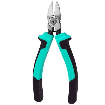
Precision peach-jaw pliers
Peach-mouth pliers, also commonly called diagonal cutters, sprue cutters, or side cutters, are a dedicated cutting tool for machining metal components and hard materials in wooden sailing ship models. They are mainly used to cut thin metal wire, sprue burrs on metal parts, hard plastic fittings, and other relatively hard materials. With strong cutting force and clean, flat cuts, they can handle the cutting needs of slightly thicker and harder metal parts that the side-cutting jaws of needle-nose pliers cannot, making them an essential tool during the metal fittings fabrication stage.
Detailed Explanation of the Two Specifications and Their Uses in Ship Modeling
1. Standard Double-Blade Version (General-Purpose Main Cutting)
The jaws have a symmetrical double-blade structure, providing high cutting force and strong durability; it is the main configuration for daily rough cutting work.
- Core uses: cutting 0.5~1.5mm copper wire, iron wire, and copper rods; trimming excess length from 9-shaped pins and copper dowel pins; trimming sprue burrs on metal castings; and cutting off excess material edges on hard plastic fittings.
- Operating points: When cutting, apply force at the base of the cutting edge for more stable force and a cleaner cut; do not use the tip of the edge to cut thick, hard wire, to avoid chipping the edge tip.
2. Thin-Blade Precision Version (Fine Flush Cutting)
Single-bevel edge with an ultra-thin cutting edge; minimal compression deformation during cutting, with flat cuts and almost no burrs, suitable for fine cutting of visible appearance parts.
- Core uses: fine cutting of bright copper wire and thin metal railing wire; trimming excess length from exposed metal parts to ensure flat cuts without secondary grinding; also suitable for handling small connecting tabs on laser-cut sheet parts.
- Operating points: Use only for fine cutting of soft metals and plastics; do not cut high-hardness steel wire to avoid chipping the thin blade.
Core Application Scenarios in Ship Modeling
1. Cutting copper wire and copper rods to length: When making railings, 9-shaped pins, and bollards, cut the wire accurately to size.
2. Trimming and shaping metal parts: Trim sprue, burrs, and excess length from copper nails, copper pins, and metal pulley mounts.
3. Cutting hard fittings to size: Cut fittings made of hard plastics, Bakelite, and other relatively hard materials.
4. Reworking waste parts: Cut off excess metal connectors and correct misaligned metal components.
Usage and Maintenance Precautions
1. Material restrictions: The standard version is only suitable for soft metals such as copper and aluminum and for plastics. Do not cut high-strength steel wire or hard steel bars to avoid chipping and deformation of the cutting edge.
2. Cutting edge guidelines: Whenever possible, use the middle and rear sections of the cutting edge for cutting; do not use the tip to cut thick, hard materials with great force, to prevent tip chipping.
3. Prohibited uses: Do not use as pliers to grip heavy objects, and do not use as a pry bar, to avoid jaw misalignment and inaccurate blade engagement.
4. Daily maintenance: After use, wipe off metal chips and glue residue from the cutting edge; apply a small amount of oil to the pivot to prevent rust and ensure smooth opening and closing.
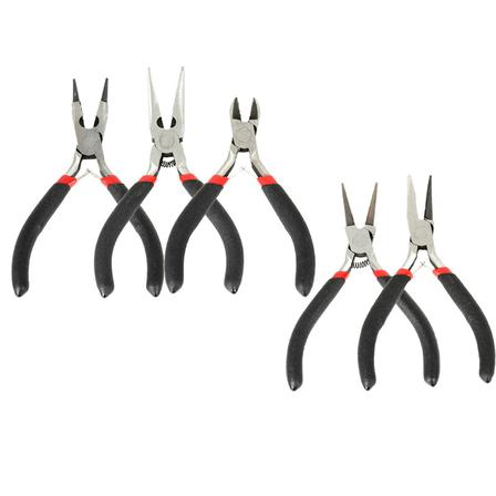
精密尖嘴钳
尖嘴钳是木质帆船模型金属舾装作业的核心夹持与塑形工具,主要解决细小金属零件夹持定位、铜线材弯折塑形、金属配件修调整形、细金属件裁切等需求,相比普通镊子夹持力更强、可承受弯折受力,是金属栏杆、索具配件、铜钉铜销加工安装阶段的必备工具。
---
各规格详解与船模用途
1. 带侧剪口有齿尖嘴钳
钳头内侧带防滑齿纹,钳身集成侧剪口,夹持稳固、功能集成度高,是日常金属作业的主力工具。
- 核心用途:
- 弯折黄铜丝、细铜棒,手工制作栏杆立柱、系缆桩、简易九字钉等金属小零件。
- 夹持九字钉、铜销钉、金属滑轮座等受力构件,辅助敲入、粘接定位,应对镊子无法承受的受力安装场景。
- 侧剪口可裁切0.8mm以内细铜丝、金属线,修整金属零件的浇口毛边。
- 调整金属舾装件角度,比如校正歪斜的栏杆、调整支索环朝向、校正锚链形态。
- 操作要点:弯折铜丝时尽量用钳头根部夹持,受力更稳;夹持粗糙结构件用齿纹面,防滑不打滑。
2. 无齿精密尖嘴钳)
钳口内侧光滑无齿,夹持时不会在工件表面留下压痕,专门负责光亮外观件的精细操作。
- 核心用途
- 夹持抛光、电镀类光亮金属装饰件,比如船铭牌金属饰边、精制炮件、黄铜装饰钉,避免夹痕破坏外观质感。
- 精细调整微型金属配件的位置与形状,比如细栏杆饰条、微型索具环的微整形。
- 穿引粗索具时辅助拉线、收紧绳结,夹持力稳定且不损伤线材表面。
- 操作要点:仅用于精细修饰作业,不要大力夹持粗硬工件,避免光滑钳面压出凹坑、失去无痕夹持能力。
---
使用与保养注意事项
1. 专钳专用:夹持木质零件、漆面构件时,必须垫一层软纸或使用无齿款,防止夹出不可逆压痕损伤表面。
2. 受力限制:迷你精密款仅适配细小金属件,禁止大力拧掰粗硬钢丝、厚金属件,避免钳头变形、咬合错位。
3. 剪口规范:侧剪口仅适合裁切铜、铝等软质细金属线,禁止剪切钢丝、硬铁丝,防止崩坏刃口。
4. 日常保养:使用后擦净钳身残留的胶水、金属屑,转轴处可滴少量润滑油保证开合顺畅。
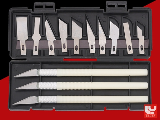
Cutter
Ship model cutting knives are core cutting tools for the assembly and processing stages of wooden sailing ship models. Used together, the two types fully cover four core needs: chiseling off board-part connection tabs, quickly cutting wooden strips, leveling joint surfaces, and trimming edge and corner details. Their cutting precision is better than that of a hand saw, and their material removal efficiency is higher than that of a carving knife, making them high-frequency must-have tools for frame making and board-part processing.
Detailed Explanation of the Two Cutting Knives and Their Uses in Ship Modeling
1. Beveled Model Pen Knife (Mainstay for General Cutting + Detail Trimming)
Pen-style grip structure with a sharp 30° beveled blade, making it the most frequently used general cutting tool in daily modeling.
- Core uses:
- Precise cutting of thin wooden strips and thin wood sheets; cuts are clean and not prone to splitting, replacing scissors for slightly harder and thicker wood.
- Trimming edge and corner details of components, removing rough edges and burrs, and leveling height differences at joint seams.
- Bevel cutting and chamfering of thin wood sheets, and fine cutting of small decorative pieces.
- Key operating points: When cutting wooden strips, keep the blade perpendicular to the wood surface, apply light pressure, and draw through at a constant speed. Never break the wood off by force, to avoid splitting along the wood grain/fibers. For detail trimming, lightly scrape with the blade tip and remove material layer by layer to prevent overcutting.
2. Flat-Blade Chisel Knife (Dedicated to Chiseling Off Board-Part Tabs + Leveling Joint Surfaces)
Also called a flat-bottom push knife or board-part separation knife. Its cutting edge is straight and wide, and its blade body is highly rigid and can withstand lateral pushing and chiseling force, specifically for chiseling and scraping tasks.
- Core uses:
- Chiseling off the connecting tabs between laser-cut board parts to quickly separate pre-cut parts such as ribs, keel, and deck without damaging the main body of the parts.
- Leveling raised glue marks and misaligned steps on joint surfaces, and scraping off laser burn marks and defects on wood surfaces.
- Cleaning excess wood from the bottom of joint notches to ensure components fit tightly without gaps during assembly.
- Key operating points: When chiseling a tab, align the blade with the base of the tab and push it horizontally along the board surface at a constant speed with even force, avoiding blade slippage that could scratch the usable area of the part. When leveling surfaces, keep the blade body at a slight angle and scrape away the allowance layer by layer.
Use and Maintenance Precautions
1. Safety precautions: The blade is sharp. During operation, point the blade away from yourself to prevent slipping and cuts. Wearing safety gloves is recommended. Put on the protective cap when not in use.
2. Use each knife only for its intended purpose: Use only on soft materials such as wood, soft plastic, and cardstock. Do not cut metal directly, to prevent edge chipping and dulling.
3. Replace blades promptly: Replace the blade promptly once it becomes dull. A dull blade makes cutting laborious and is more likely to slip, which in turn makes wood edge chipping and operational errors more likely.
4. Storage and protection: Store blades and knife bodies in a dedicated case to avoid the cutting edge colliding with hard objects, and to prevent small blades from scattering and getting lost.
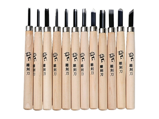
Mini carving knife
This is a cutting tool specially used in wooden sailing ship model making to remove excess wood. It lies between rough cross-cutting with a hand saw and fine sanding with sandpaper, and can perform thin wood cutting, edge and corner shaping, notch trimming, groove machining, detail carving, and other operations. It offers higher precision than a saw and faster stock removal than sandpaper, making it an essential tool for frame finishing and fitting part shaping.
Detailed Explanation of Each Blade Type and Corresponding Uses in Ship Modeling
1. Flat chisel (large-area surface stock removal)
The cutting edge is straight and regular, with a large cutting contact area and the highest stock removal efficiency.
- Core uses: Quickly level rough sawn cross-sections of square timber, level the bottom surfaces of joint notches between the keel and ribs, and remove large areas of excess wood; it is the main tool in the rough shaping stage.
- Suitable scenarios: Rough shaping of square timber, leveling of large notches, and removal of excess on thick wood.
2. Skew chisel (general-purpose edge-trimming workhorse)
The cutting edge is angled, and the tip is sharp and flexible, balancing stock removal efficiency and precision; it is the most frequently used general-purpose type.
- Core uses: Trim component edges and corners, machine angled notches, shave cured glue marks in joints, and finely adjust part dimensions.
- Suitable scenarios: Rib side edge shaping, fitting part edge trimming, and fine machining of angled components.
3. Gouge (dedicated to curved/concave groove machining)
The cutting edge is arc-shaped, specifically for machining curved surfaces and arc-shaped grooves.
- Core uses: Dig semicircular slots, trim the curved contours of the bow and stern, machine mast mounting grooves, and shape the outer profiles of cylindrical parts.
- Suitable scenarios: Curved decorative parts, semicircular notches, and cylindrical component shaping.
4. V-parting tool (fine-line/V-groove carving)
The cutting edge is V-shaped triangular, specifically for engraving lines and machining narrow grooves.
- Core uses: Carve simulated seam lines for hull plank joints, machine narrow V-shaped grooves, carve decorative details, and trim excess wood in internal corner dead areas.
- Suitable scenarios: Simulated wood grain engraved lines, narrow grooves on gunport frames, and decorative carving detail machining.
5. Pointed chisel (fine dead-corner shaping)
The tip is sharp and slender, allowing it to reach into narrow gaps for work.
- Core uses: Clean small notch dead corners, shape the contours of miniature parts, and remove excess glue marks and wood chips from gaps.
- Suitable scenarios: Shaping miniature fitting parts and fine trimming of narrow gaps.
Quick Selection Guide by Part
1. Keel, rib notches, hull trimming; core tools: flat chisel, skew chisel; machining stage: rough shaping after sawing.
2. Curved contours of bow and stern; core tools: gouge, skew chisel; machining stage: fine contour shaping.
3. Simulated wood grain and decorative engraved lines on the hull; core tool: V-parting tool; machining stage: appearance detail machining.
4. Edge and corner shaping of small fitting parts; core tools: skew chisel, pointed chisel; machining stage: fine trimming before assembly.
5. Groove and semicircular slot machining; core tool: gouge; machining stage: fine structural machining.
Usage and Maintenance Precautions
1. Stock removal principle: Follow the principle of small amounts and multiple passes, removing the allowance layer by layer. Never cut too deep in one pass to avoid wood splitting and over-cutting.
2. Cutting direction: Cut along the wood grain as much as possible; cutting against the grain can easily cause wood fibers to fuzz and edges to chip.
3. Safety rules: The blade is sharp. During operation, point the blade away from yourself to prevent slipping and cuts. Wearing safety gloves is recommended; put on the protective cap when not in use.
4. Dedicated tool for dedicated use: Use only on soft materials such as wood and soft plastic. Do not cut metal or hard cardboard to avoid rapid edge wear and chipping.
5. Cutting edge maintenance: When the blade becomes dull, hone it sharp with a fine oilstone along the cutting edge angle; a dull blade requires more effort to cut and slips easily, making operating mistakes more likely.
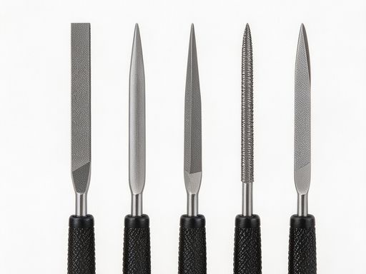
File
Files are the core shaping tools that bridge rough saw cutting and fine sandpaper sanding. They mainly solve problems that sandpaper struggles to handle efficiently, such as rough and uneven kerfs after sawing, insufficient precision of joint notches, shaping of irregular contours, and edge trimming and deburring of micro-hole inner walls. Through different tooth patterns, they adapt to various configurations such as flat surfaces, curved surfaces, internal corners, and round holes. They are essential tools in the frame finishing and component shaping stages.
---
Detailed Explanation of File Types and Corresponding Uses in Ship Modeling
1. Flat File (Mill File) · Mainstay for Flat-Surface Shaping
The file body is flat, with cutting teeth on both faces, making it the most frequently used basic model.
- Core uses: leveling sawn end faces of wood strips, trimming joint notches on keels and frames, leveling the side edges of deck planks, and correcting large-area flatness deviations; after sawing, use a flat file first to quickly level the coarse allowance, then transition to sandpaper sanding.
- Selection advice: choose one medium-cut and one fine-cut file each; coarse cut removes stock, fine cut smooths the surface.
2. Half-Round File · for Curved Surfaces/Arcs
One face is flat and the other is rounded, handling both flat and curved work.
- Core uses: shaping the curved contours of the bow and stern, sanding mast tapers and round components, trimming curved edges of frames, and cutting semicircular grooves; the curved face conforms to component curves, and shaping efficiency is much higher than with sandpaper.
- Selection advice: prefer a medium-width half-round file, suitable for most curved components.
3. Triangular File · for Internal Corners/Slots
The cross-section is triangular, with cutting teeth on all three edges, specifically for included angles and narrow slots.
- Core uses: trimming the internal corners of frame slots, cutting V-shaped notches, straightening and trimming the inner walls of narrow slits, and cleaning excess glue marks and wood dust from dead corners at joints; it can perform precision correction of right-angle joints and handle areas that flat files cannot reach.
4. Round File · for Round Holes/Curved Slots
The file body is cylindrical, with cutting teeth all around, suitable for round holes and curved slots.
- Core uses: enlarging rigging hole diameters, trimming burrs on the inner walls of drilled holes, making round pin holes, and refining curved grooves; when a hand drill leaves holes too small or inner walls not smooth, use a round file for fine hole enlargement and edge trimming.
- Selection advice: keep 1.0 mm and 2.0 mm diameters on hand, matching common hole diameters in ship modeling.
5. Knife File (Supplementary) · for Narrow Gaps/Fine Edge Trimming
The cutting edge is narrow and thin like a blade, suitable for finishing extremely narrow gaps.
- Core uses: trimming narrow gun-port slots, slotting thin wood strips, and trimming fine grooves on railing bases; for fine shaping in ultra-narrow areas, it is an advanced supplementary item and not essential for beginner projects.
---
Processing Sequence by File Cut Coarseness
File cut coarseness corresponds to different processing stages and connects logically with sanding, following the “coarse to fine” principle:
1. Coarse-cut file: quickly remove large stock after sawing and correct large deviations, leaving 0.1–0.2 mm finishing allowance.
2. Medium-cut file: the main shaping operation, leveling surfaces and correcting contours to achieve dimensional accuracy close to the finished part.
3. Fine-cut file: fine-finish and smooth surfaces, remove coarse-file scratches, and provide a transition to subsequent sandpaper sanding.
> After shaping wooden components, sand finely in the sequence 240# → 400# → 600# to obtain a flat and smooth surface.
---
Quick Reference for File Selection by Part
1. Keel, frame notches, and end faces; core files: flat file, triangular file; cut selection: coarse cut → medium cut.
2. Curved contours of bow and stern; core files: half-round file; cut selection: medium cut → fine cut.
3. Masts and cylindrical parts; core files: half-round file, round file; cut selection: medium cut → fine cut.
4. Edge trimming and hole enlargement of rigging holes and pin holes; core files: round file; cut selection: fine cut.
5. Gun ports, narrow slots, and internal corners; core files: triangular file, knife file; cut selection: medium cut → fine cut.
6. Fine finishing of small fitting parts; core files: full set of fine needle files; cut selection: fine cut.
---
Usage and Maintenance Precautions
1. Filing direction: push and apply pressure along the wood grain; lift the file off the wood on the return stroke to avoid filing against the grain, which can cause wood fibers to fuzz and edges to tear out.
2. Force principle: advance with light pressure and steady speed, relying on the file teeth to cut naturally; excessive force can cause file teeth to chip off and wood to crack.
3. Timely chip removal: wood dust packed between file teeth reduces cutting efficiency; clean with a wire brush along the tooth direction; do not blow chips off with your mouth.
4. Dedicated use: wood files are only for wood and soft plastics; do not file metal parts directly, to avoid rapid tooth wear and chipping; when filing brass pins or metal parts, keep a separate metal-specific file.
5. Storage protection: file teeth are relatively brittle; avoid mixing and bumping with hard objects such as wrenches and pliers to prevent tooth tips from chipping.
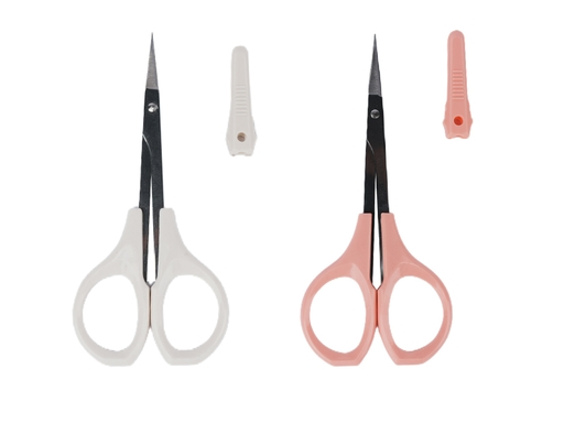
剪刀
剪刀是木质帆船模型制作中负责软质材料裁切的基础工具,主要用于薄木皮修型、各类索具线剪断、帆布料修剪等作业,相比美工刀操作更灵活安全,切口整齐不易散边,是舾装、索具制作阶段的必备工具。
各规格用途详解
1. 尖头精密直剪
刃口尖细平直,闭合精度高,是日常制作使用率最高的基础款。
- 核心用途:裁切细棉线、尼龙索具、薄木皮、装饰贴纸、细小帆布条;尖头可深入狭窄缝隙,精准修剪索具线头、木皮毛边。
- 适配场景:0.1~1mm线径的各类索具、0.5mm以内薄装饰木皮、船铭牌贴纸、细小帆装零件。
2. 弯头精密剪(曲线/死角专用款)
刃口呈向上弯曲的弧形,裁剪时刀身不遮挡切割线视线,专门应对曲线轮廓与狭窄空间作业。
- 核心用途:剪切弧形木皮装饰件、异形帆边、曲面船壳装饰木片;也适合舷墙内侧、栏杆间隙等视线受阻位置的线头修剪。
- 适配场景:曲线轮廓木皮、弧形帆边、死角位置修边、异形装饰件裁切。
使用与保养注意事项
1. 专剪专用:精密剪刀仅用于软质材料,禁止剪切金属丝、硬塑料、厚卡纸,避免刃口崩口变钝。
2. 裁切技巧:精细作业用刀尖部位精准控制;裁切稍粗的绳索、稍厚的木皮时用刀刃根部发力,切口更整齐省力。
3. 木皮裁切要点:沿木纹方向匀速施力剪断,避免强行撕扯导致木纤维劈裂、出现毛边。
4. 保养收纳:使用后擦净刃口残留的木屑、胶水,套上保护套存放,防止磕碰损坏刀尖刃口。
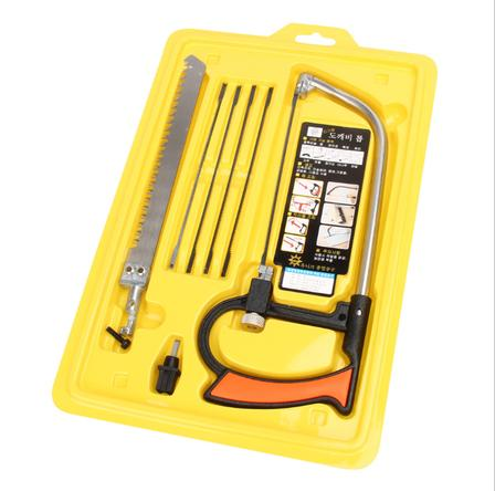
船模专用小手工锯
小手工锯是木质帆船模型前期下料与粗加工阶段的核心切割工具,主要解决大尺寸木方截断、龙骨与肋骨豁口加工、厚木料精细裁切的需求,相比美工刀更适配厚料、硬木作业,切口规整且不易崩边,是骨架制作、木方下料的必备工具。
各部件对应用途详解
1. 宽齿钢锯条(木方截断主力)
搭配锯架使用,是厚木料、大规格木方快速截断的主力配置,应对龙骨、横梁等大尺寸实木料的粗下料效率最高。
- 核心用途:较大规格木方/实木条截断、厚层板裁切、粗坯料快速修型。
- 操作要点:粗截断预留0.2~0.5mm打磨余量,后续用砂纸找平切口;切割时保持锯条垂直,避免锯条弯折断裂。
2. 细齿锯条(豁口/精细裁切专用)
齿距细密、锯路窄,专门用于精细开槽、加工拼接豁口、裁切细木条,是肋骨与龙骨拼接位加工的核心配置。
- 核心用途:龙骨肋骨拼接豁口加工、细木条精准裁切、装饰件开槽、小型榫头制作。
- 操作要点:切割前用刻针标记开槽边线,匀速轻推控制深度,避免锯偏崩边;加工深豁口时定期退锯排屑。
3. 钢丝线锯条(曲线/异形切割补充)
细钢丝材质,可灵活转向,专门应对曲线、异形轮廓与镂空切割,是船艏船艉异形板、甲板开窗等异形构件加工的补充配置。
- 核心用途:船艏船艉异形板切割、甲板镂空开窗、肋骨弧形轮廓修型、内部异形构件加工。
- 操作要点:安装时拉紧锯条,沿标记线匀速移动,不要强行掰弯锯条,避免断丝。
---
通用使用注意事项
1. 所有锯条安装时需拉紧固定,松垮的锯条极易跑偏、断裂。
2. 切割硬木(红花梨、榉木)时放慢节奏,避免蛮力推锯导致锯条崩齿。
3. 薄木片、小构件切割时,可用镊子或夹具固定木料,避免手持晃动导致切口歪斜。
4. 锯条变钝后及时更换,钝锯条不仅切割费力,还容易崩裂木料边缘。
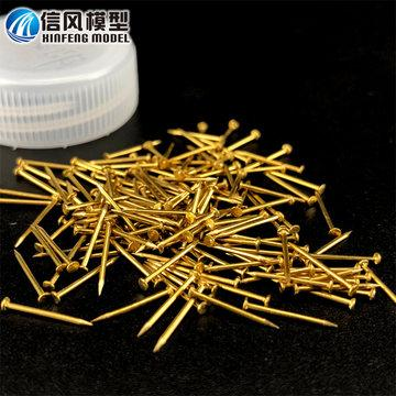
Miniature copper nail category
Copper nail categories for ship models are core accessories for structural reinforcement and simulated fittings of wooden sailing ship models. Used together with mini hammers, pin vise drills, and tweezers, they serve both structural fastening and appearance simulation. The complete system covers three major categories—structural fastening, exposed decoration, and dedicated fittings—fully covering the fabrication needs of all scenarios from the main frame to detail decoration.
---
I. Composition of the Complete Nail Set + Supporting Tool Collection
6 nail types + 4 supporting installation tools, corresponding to all modeling scenarios. The complete list is as follows:
> Supporting tools: mini double-head hammer (nylon + brass double heads), precision pin vise drill, straight-tip stainless steel tweezers, tungsten carbide locating scribe.
> Nail types: copper cylindrical dowel pins, round-head brass nails, countersunk-head brass nails, wooden dowel pins, simulated decorative rivets, brass figure-nine nails.
---
II. Full Analysis of Core Nail Types
1. Copper cylindrical dowel pins (mainstay for hidden structural positioning)
Headless pure cylindrical copper rods rely on an interference fit with the wood for fastening. After installation, they are completely hidden with no exposed marks, offering high positioning accuracy and good structural strength.
- Core uses: keel-to-rib joining and positioning, internal fixing of mast bases, movable pivot shafts of gun carriages, hidden component joining and reinforcement.
- Common specifications: 0.6 mm / 0.8 mm / 1.0 mm / 1.2 mm / 1.5 mm / 2.0 mm.
- Matching drill bits: pilot hole diameter equal to or 0.05 mm smaller than the pin diameter to achieve an interference fit.
2. Round-head brass nails (general fastening + exposed simulation)
Semicircular head, brass material is rustproof and corrosion-resistant, with moderate hardness and not easy to bend. They balance structural fastening and appearance simulation and are the most frequently used general-purpose type.
- Core uses: exposed fastening of hull planking, bulwarks, rubbing strakes, and fittings; the nail heads directly serve as simulated details.
- Common specifications: 0.5 mm / 0.6 mm / 0.7 mm / 0.8 mm / 1.0 mm / 1.2 mm.
- Matching drill bits: pilot hole diameter = nail diameter − 0.1 mm, ensuring holding power while avoiding splitting the wood.
3. Countersunk-head brass nails (dedicated for flush surface fastening)
Tapered countersunk head design; after driving in, they are flush with the wood surface with no protrusion and do not affect subsequent sanding and painting processes.
- Core uses: deck planking installation, exposed hull nails, fastening of flat decorative parts, and exposed surfaces requiring extreme flushness.
- Common specifications: 0.6 mm / 0.7 mm / 0.8 mm / 1.0 mm.
- Matching drill bits: pilot hole diameter = nail diameter − 0.1 mm. For large-scale models, a chamfer bit can be used to countersink the hole.
4. Wooden dowel pins (fully hidden, traceless reinforcement)
Solid wood round rods of the same material as the model; after bonding, they blend into the base wood with no color difference and no metallic foreign-body feel.
- Core uses: hidden positioning of internal frames, reinforcement of deck strip joints, and appearance structures where exposed metal is not allowed.
- Common specifications: 0.8 mm / 1.0 mm / 1.2 mm / 1.5 mm.
- Matching drill bits: pilot hole diameter 0.1–0.2 mm smaller than the dowel diameter; bonding with wood glue gives higher strength.
5. Simulated decorative rivets (pure appearance detail type)
Extremely fine flat-bottomed copper nails/copper beads with no actual structural load-bearing; used only to reproduce the visual details of rivets on real ships.
- Core uses: cannon hoop rivets, ship nameplate decoration, simulation of metal fittings; in small-scale models they replace real nails to avoid splitting thin plates.
- Common specifications: 0.3 mm / 0.4 mm / 0.5 mm.
- Installation method: shallow hole + cyanoacrylate adhesive; no need to drive deeply.
#6. Figure-nine nails (dedicated nails for mooring fittings)
Also called hook nails or mooring nails; made of brass and shaped like a "9" as a whole, with one end being a straight shank that can be driven in for fastening and the other end a curved hook for hanging ropes and mooring lines. They are an iconic fitting of ancient sailing ship rigging.
- Core uses: simulate mooring bitts and fairlead hooks on real ships; used for rope attachment points on decks and bulwarks, fixing the ends of anchor chains and shrouds, greatly improving the realism of fittings.
- Common specifications:
- Large-scale models (1:20–1:48): shank 0.8–1.2 mm, hook inner diameter 2–4 mm.
- Medium-scale models (1:50–1:80): shank 0.6–0.8 mm, hook inner diameter 1.5–2.5 mm.
- Small-scale models (1:96–1:150): shank 0.4–0.5 mm, hook inner diameter 1–1.5 mm.
- Key installation points: drill corresponding pilot holes in advance, apply a small amount of cyanoacrylate adhesive to the shank and drive it in, orient all hooks toward the outboard side, and arrange them evenly along the bulwarks and deck edges.
---
III. Specification Selection Table by Model Scale
| 1:20–1:48 Large-scale large ship models | Structural pins: 1.0–2.0 mm | Exposed fastening nails: 0.8–1.2 mm | Figure-nine nail shank: 0.8–1.2 mm | Matching drill bit specifications: 0.8 / 1.0 / 1.8 mm | Typical applications: main frame, thick hull planking, mast base, large gun carriage |。
| 1:50–1:80 | Medium-scale mainstream ship models | Structural pins: 0.7–1.2 mm | Exposed fastening nails: 0.7–0.8 mm | 0.6–0.8 mm | Matching drill bit specifications: 0.6 / 0.7 / 1.0 mm | Typical applications: hull planking, deck nails, bulwarks, rib positioning, general fittings |。
| 1:96–1:150 | Small-scale fine ship models | Structural pins: 0.4–0.8 mm | Exposed fastening nails: 0.4–0.6 mm | Figure-nine nail shank: 0.4–0.5 mm | Matching drill bit specifications: 0.3 / 0.5 / 0.7 mm | Typical applications: decorative rivets, fine railings, miniature gun parts, small mooring points |。
---
## IV. Detailed Uses and Specification Selection by Part
1. Main frame (keel/ribs/beams)
- Core function: structural positioning + deformation-resistant reinforcement, compensating for the load-bearing shortcomings of purely glue-bonded joints.
- Nail types: copper cylindrical dowel pins / wooden dowel pins (fully hidden, not exposed).
- Corresponding specifications: large scale 1.5–2.0 mm; medium scale 1.0–1.2 mm; small scale 0.6–0.8 mm.
- Key operation points: the dowel pins pass through the keel and ribs; apply wood glue to both ends and drive them in; after curing, sand flush so they are completely hidden without marks.
2. Hull planking
- Core function: assist glue in fixing hull planks, prevent debonding due to thermal expansion and contraction; reproduce the simulated effect of exposed nails on real ship planking.
- Nail types: round-head brass nails / countersunk-head brass nails (choose countersunk for a flush finish).
- Corresponding specifications: large scale 1.0–1.2 mm; medium scale 0.8 mm; small scale 0.5–0.6 mm (or paint dots to simulate fake nails).
- Key operation points: distribute evenly along the plank seams; when hammering thin planks, the back must be backed with scrap wood to prevent splitting.
3. Deck system
- Core function: fix deck planking strips (for the second deck layer, second-layer hull planking strips can be used), simulating the real deck nail installation pattern.
- Nail types: countersunk-head brass nails (flush with the deck after installation); decorative rivets for small scales.
- Corresponding specifications: large scale 0.8–1.0 mm; medium scale 0.6–0.8 mm; small scale 0.4–0.5 mm.
- Key operation points: for large scales, pre-countersink with a chamfer; position nails symmetrically along both sides of the deck strips for higher realism.
4. Bulwarks and mooring fittings
- Core function: fix bulwark planks and rubbing strakes, and reproduce the details of mooring attachment points.
- Nail types: round-head brass nails (structural fastening) + figure-nine nails (mooring attachment points).
- Corresponding specifications:
- Fastening nails: large scale 1.0–1.2 mm; medium scale 0.7–0.8 mm; small scale 0.5–0.6 mm.
- Figure-nine nails: large scale shank 0.8–1.2 mm; medium scale 0.6–0.8 mm; small scale 0.4–0.5 mm.
- Key operation points: the hooks of figure-nine nails face outboard and are evenly arranged; ropes hang naturally after being hooked, reproducing the real mooring effect.
5. Mast and rigging bases
- Core function: fix load-bearing components such as mast bases, pulley block seats, and shroud rings.
- Nail types: copper pins (internal positioning) + round-head copper nails (exposed fastening).
- Corresponding specifications: large scale 1.2–1.5 mm pins + 1.0 mm round-head nails; medium scale 0.8–1.0 mm pins + 0.8 mm round-head nails; small scale 0.6–0.8 mm pins + 0.6 mm round-head nails.
- Key operation points: the mast base is a load-bearing position; dual fixation with pins + glue is recommended to prevent loosening from rigging tension later.
6. Cannons and movable fittings
- Core function: gun carriage pivot shafts, anchor chain fixing, movable hatch hinges.
- Nail types: copper cylindrical dowel pins (as pivots) + miniature round-head nails (fixing gun carriages) + decorative rivets (simulating cannon hoops).
- Corresponding specifications: large scale 1.0–1.2 mm pins; medium scale 0.6–0.8 mm pins; small scale 0.4–0.5 mm pins.
- Key operation points: pivot pins need about 0.05 mm clearance to ensure smooth rotation without sticking.
7. Fine decorative parts (railings, ship nameplates)
- Core function: ultra-realistic fastening, replacing glue to avoid glue overflow contamination.
- Nail types: ultra-fine decorative rivets / 0.4–0.6 mm miniature round-head nails.
- Scope of application: only for large-scale collector-grade models; ordinary practice models can simply be bonded with cyanoacrylate adhesive.
---
V. Supporting Tools and Installation Operation Specifications
1. Mini double-head hammer: one end is a soft nylon head (for hammering wood surfaces, preventing dents and chipped edges), and the other is a brass head (for hammering nails, less likely to bend fine nails).
2. Precision pin vise drill: manually drill pilot holes of the corresponding size at low speed; small holes are precise without chipping, protecting thin wood.
3. Straight-tip tweezers: hold fine nails in alignment, preventing fingers from blocking the view and the nail shank from tilting.
4. Locating scribe: mark positions on the wood surface in advance to prevent the drill bit from slipping off.
Standard Installation Procedure
1. Positioning and marking: use a scribe to mark hole positions on the wood surface and make shallow dimples to prevent the drill bit from slipping.
2. Matching pilot hole: select the corresponding drill bit according to nail diameter, drill vertically with a pin vise drill; hole depth should be 0.5–1 mm deeper than the nail length to leave space for wood chips.
3. Holding nail in alignment: use tweezers to grip the nail shank and align it with the hole; tap 1–2 times to secure it before releasing.
4. Tapping into place: tap evenly and lightly with the brass hammer head; reduce force near the end to avoid damaging the wood surface.
5. Final reinforcement: exposed nails can be reinforced with a small dot of cyanoacrylate adhesive; hidden dowel pins bonded with wood glue have higher strength.
Key Pitfalls to Avoid
- Never hammer nails directly without drilling pilot holes; this can easily split thin wood sheets and cause splitting along the grain.
- When hammering thin wood or wood edges, the back and sides must be supported with scrap wood to prevent chipped edges.
- For small-scale thin plates, preferentially use the "fake-nail method": dip a needle tip in dark paint and dot the nail positions, completely avoiding the risk of splitting.
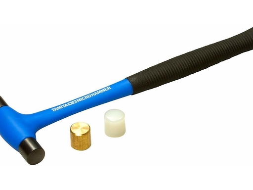
小锤
模型迷你小锤(也常称钟表锤、微型榔头)是木质帆船模型装配阶段的专用敲击工具,主要解决板件拼接归位不实、微型钉类/销钉手工按入不到位、紧配构件手工无法压入的问题,依靠轻量可控的敲击力完成精细装配作业,同时避免大力敲击损坏薄木料与精细零件。
核心锤头类型与船模对应用途
1. 尼龙/橡胶软锤头
锤头带有一定弹性,敲击时不会在木料表面留下凹痕、不会崩裂木边,是日常制作使用率最高的款式。
- 适用场景:轻敲船壳外板、甲板木条使拼接缝紧密贴合;将肋骨轻轻敲入龙骨卡槽就位;拍平轻微起翘的薄木片;校正轻微错位的拼接结构
2. 黄铜锤头
黄铜硬度适中,比普通钢锤质地更软,敲击时不易敲弯细铜钉、不易砸坏金属配件。
- 适用场景:敲入微型铜钉、木销钉、金属固定销,固定桅杆底座、炮架、缆桩等受力构件;配合冲子裁切薄铜片、皮革饰件。
3. 钢制锤头
硬度高、敲击力强,仅用于大比例船模的粗销钉、厚构件敲击,新手不推荐主力使用,蛮力极易敲裂薄木料。
船模使用关键注意事项
1. 发力原则:全程轻敲为主,依靠锤头自重下落发力,禁止大力抡锤;1~2mm薄木片抗冲击能力弱,蛮力极易造成木料沿木纹劈裂。
2. 材质对应规则:敲击所有木质表面必须使用软头锤,仅在敲击金属钉、金属配件时使用黄铜/钢质锤头。
3. 钉类操作规范:所有钉类作业必须提前用手捻钻打好对应尺寸的引孔;敲细钉时先用镊子扶住钉身对准孔位,轻敲固定后再松手,防止钉子歪斜刮花木料。
4. 边缘敲击防护:敲击木料边缘位置时,可垫一块同厚度废木再敲,避免直接敲击导致木边崩缺。

粘胶工具体系(胶水 + 点胶辅助工具)
这套工具整体解决木质帆船模型制作中木质主体结构粘接强度不足、微小零件对位粘接易移位、涂胶量失控溢胶污染木纹、异材质(木/金属/塑料)粘接不牢、索具绳头易散/微孔易裂**五大核心问题,是保证结构牢固度、外观整洁度与细节精度的关键配套工具,需配合镊子、手捻钻等工具协同使用。
---
一、核心胶水选型 & 对应解决的场景问题
1. 木工白乳胶(PVA木胶)
解决的核心问题:木质构件大面积拼接的结构强度与缝隙填充问题,胶水可渗入木材孔隙,固化后粘接强度接近木材本身,兼具韧性,不会像快干胶那样发脆断裂。
- 船模适用场景:龙骨与肋骨拼接、船壳外板大面积铺贴、甲板木条拼接、内部木质支撑结构等所有主体受力木质构件粘接。
- 特点:可打磨、可上色,无腐蚀性,不会损伤木料;常温下1~2小时初固,24小时完全固化,粘接后需临时夹持固定。
- 选型要点:优先选D3级家具/模型专用木胶,粘稠度适中;不推荐建筑用大桶稀胶,水分大易导致薄木片变形。
2. 模型瞬干胶(CA氰基丙烯酸酯胶)
解决的核心问题:微小零件快速定位、索具绳头锁固、微孔补强,解决小零件用木胶固化慢、易移位、对位难,以及细孔、缝隙无法补胶的痛点。
- 细分规格与对应场景:
- 低粘度(稀款):渗透力极强,用于索具绳头收束防散、钻孔内壁加固、拼接缝隙渗透补强;顺着缝隙滴入即可快速渗入木材孔隙。
- 中高粘度(稠款):不流淌、不扩散,用于粘贴栏杆柱、缆桩、滑轮、炮窗饰条等外露细小零件,不会大面积流淌污染木纹表面。
- 注意事项:固化速度快(几秒到几十秒),但固化后材质偏脆,不耐大力拉扯;操作不当易在木料表面留下泛白印,外露面需严格控制用量。
- 选型建议:船模常备低粘度+中粘度各一瓶,分别对应渗透补强和零件粘接。
3. 环氧树脂AB胶
解决的核心问题:不同材质(木+金属、木+塑料)的高强度粘接,以及大缝隙填充、关键受力位结构补强,解决单一胶水粘不牢异材质、缝隙填不满强度不足的问题。
- 船模适用场景:桅杆金属底座与木甲板固定、铜质栏杆与木质基座粘接、大比例船模龙骨受力位补强、破损木质构件修补。
- 特点:固化后强度极高,防水耐潮,可填充较大缝隙;缺点是固化慢(慢干款30分钟初固,24小时全固),需按比例混合,操作略繁琐。
- **选型要点:优先选慢干型(30分钟初固),预留足够的精细对位时间;快干款操作窗口太短,极易在对位过程中固化失误。
4. 酒精胶
解决的核心问题:极薄木片、装饰纸的无痕粘接,解决普通木胶水分大导致薄木片吸水变形、起翘的问题。
- 船模适用场景:船铭牌、装饰木纹纸、0.5mm以内极薄蒙皮的粘贴。
- 特点:依靠酒精挥发固化,水分含量极低,木料不易变形;固化后透明无痕迹,但强度一般,仅适合非受力装饰件。
---
二、点胶辅助工具 & 对应解决的问题
1. 塑料点胶针头
解决的问题:瞬干胶原装瓶口出胶量过大,无法精准涂到细微位置,极易溢胶污染表面。
- 用法:套在瞬干胶瓶口,可精准把胶水滴到0.5mm级的小孔、零件边缘,实现“点到为止”的涂胶量控制。
- 选型:常备0.4mm、0.8mm两种规格,细针头配低粘度胶做渗透,粗针头配稠胶粘零件;用完及时拔下清理,防止胶水固化堵头。
2. 1ml/2ml一次性塑料注射器
解决的问题:木胶、环氧树脂的定量涂抹,以及深孔、隐蔽缝隙内部的注胶需求,解决胶水送不到死角的问题。
- 用法:抽取胶水后推动推杆精准控制出胶量,适合给肋骨拼接缝、船壳内部死角注胶;也可用于AB胶按比例精确取量,避免配比不准导致固化失败。
- 注意:禁止用于抽取瞬干胶,胶水会在针管内快速固化堵死。
3. 尖嘴点胶瓶
解决的问题:大工作量木胶涂抹的便利性与控量问题,替代原装大瓶操作更灵活。
- 用法:将木胶分装到尖嘴挤压瓶中,挤压瓶身即可均匀出胶,适合大面积铺船壳、粘甲板条时施工;瓶口可按需裁剪粗细,适配不同涂胶宽度。
4. 溢胶清理工具
- 无尘细棉签 + 牙签:解决溢胶即时清理问题。木胶溢胶用微湿棉签直接擦掉;瞬干胶未完全固化时,用牙签尖部刮掉多余胶珠,避免大面积擦拭扩散污染。
- 瞬干胶除胶剂:解决固化后溢胶、表面泛白印的清理问题。取少量滴在棉签上轻擦,可去除表面胶痕;注意少量使用,避免溶解后续的漆面。
5. 固定辅助工具
- 美纹纸:解决薄木片涂胶后移位、起翘的问题,对位后沿边缘粘贴临时固定,固化后撕掉不留胶痕。
- 小型木工夹/长尾夹:解决主体结构粘接的加压固定问题,保证拼接面紧密贴合,最大化粘接强度。
---
三、船模粘胶通用操作原则
1. 选材原则:主体受力结构用木胶保强度,细小外露零件用瞬干胶提效率,异材质粘接用环氧防脱落。
2. 用量原则:少量多次,宁少勿多。外露表面粘接优先少涂,胶水溢出污染木纹后修补成本极高。
3. 预处理原则:粘接面提前用细砂纸轻磨去毛刺、擦净灰尘,油污、灰尘会大幅降低粘接强度。
4. 薄件防变形原则:1mm以内薄木片涂胶,尽量两面均匀薄涂,不要只涂单面,避免单面吸水导致弯曲起翘;粘完立即用重物压平或美纹纸固定。
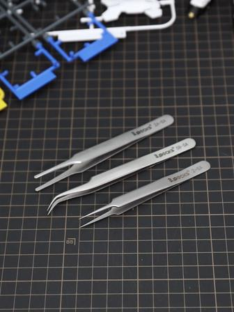
Precision tweezers
Tweezers are a high-frequency precision operation tool in ship model building. Different tip configurations correspond to different component sizes and operation scenarios. They are mainly used for holding and positioning micro parts, glue fixing, rigging threading, and cleaning hard-to-reach areas. It is recommended to keep one of each commonly used specification to cover all modeling needs.
Basic Commonly Used Set (Straight-Point/Bent-Tip/Flat-Tip Three-Piece Set)
Beginners in ship model building should equip these three first; they can cover more than 90% of precision operation scenarios.
---
1. Straight-Point Precision Tweezers (Essential Mainstay Version)
The tips are fine, straight, and flat, and close tightly at the ends, providing the highest holding precision. They are a general-purpose mainstay tool for daily modeling.
- Core uses in ship model building
- Hold miniature stanchions, small pulleys, bollards, gunport trim strips, and other small components for precise positioning and gluing
- Assist in threading fine cotton thread/nylon rigging line within 0.5 mm, feeding the thread end into 0.6–1.0 mm rigging holes
- Clean fine debris such as wood chips on the inner walls of drilled holes and excess glue marks in seams
- Selection tips: Prefer 304 stainless steel models; the tips should close without gaps; a length of 11–13 cm provides the most stable one-handed grip.
2. Bent-Tip Precision Tweezers (Essential for Deep/Curved-Surface Operations)
The tips are bent upward at 30°–45°, avoiding the tweezer body blocking the line of sight; specially suited for narrow, deep locations.
- Core uses in ship model building
- Glue parts and secure rigging knots in narrow areas such as the inside of the hull and gaps between frames.
- Install concealed components below the deck and inside the cabin without the tweezer body obstructing the view.
- Hold small glue-dipped parts to prevent glue from sticking to fingers and affecting operation.
- Selection tips: A 30° bent tip is the most versatile; tips must close tightly without misalignment.
3. Flat-Tip/Flat-Nose Tweezers (Dedicated for Holding Wood Strips)
The tips are flat and wide, with a large contact area and low pressure, so they will not crush or mar the surface grain of thin wood sheets or soft wood.
- Core uses in ship model building
- Hold thin hull planking and deck strips to align seams and prevent shifting before the glue cures.
- Position and fix ship nameplates and large-area decorative pieces with even force, making it less likely to damage parts.
- Hold small pieces of sandpaper to sand edges, corners, the inside of gunports, and other hard-to-reach areas that fingers cannot touch.
- Selection tips: Tip width of 3–5 mm is appropriate; edges should be smooth and burr-free to avoid scratching wood and painted surfaces.
---
4. Self-Locking Reverse Tweezers (Free Both Hands During Long-Term Fixing)
With a reverse self-locking mechanism, squeeze the tweezer body to open and release to automatically clamp; no need to continuously squeeze throughout.
- Core uses in ship model building
- Hold parts fixed for long periods during glue curing to free both hands for other steps.
- Provide heat-insulating holding when soldering brass railings and heat-shaping brass wire components.
- Fix multiple parts separately when gluing them simultaneously, improving batch installation efficiency.
- Selection tips: Prefer stainless steel self-locking models with moderate clamping force to avoid crushing thin wood sheets under 1 mm.
---
Purchasing and Usage Precautions
1. Precision first: The core performance of tweezers is tip closure. Qualified precision tweezers should have no gap and no misalignment at the tips after closing, so they can stably hold fine threads and micro parts.
2. Material first choice: 304 stainless steel: rust-resistant and with good elasticity; it is not easy to deform or misalign after long-term use. Ordinary sheet-iron models are not recommended, as they will become loose and lose accuracy after only a few uses.
3. Usage prohibitions: Do not use precision tweezers to hold hard objects or twist/bend parts, as this can easily cause tip misalignment and chipping at the tips. After gluing, promptly wipe residual glue off the tips to avoid sticking to tiny parts next time.
4. Storage protection: Put on tip protectors when not in use to prevent collisions from blunting the tips and also prevent puncture injuries.
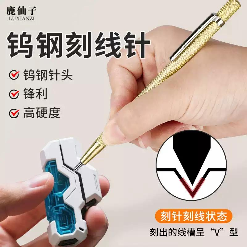
Engraving needle (scriber)
Model scribers are a core tool used in wooden sailboat model making for high-precision scribing and point positioning. They use a hard, sharp metal needle tip instead of a pencil to scribe extremely fine marks on wood and plywood surfaces. When used with a straightedge or set square, the scribing error can be controlled to the 0.1 mm level. They are an essential small item for ensuring the accuracy of hull planking cutting, hole positioning, and component assembly.
---
I. Common Types and Selection
1. Pen-style tungsten carbide scriber (primary first choice)
This is the most commonly used style in ship model making. The pen-shaped handle provides a stable grip, and the tungsten carbide tip has high hardness and wear resistance and is not easily dulled. It is suitable for hardwoods, plywood, and balsa, and is the primary tool for daily cutting and scribing.
- Core advantages: The tip is sharp, and the scribed lines are thin and uniform. It is 3–5 times more durable than ordinary stainless steel scribers.
- Key specifications: A tip diameter of 0.1–0.3 mm is preferable. Models with a protective cap are preferred for safer storage.
2. Scriber + center punch combination (highly recommended for ship model drilling)
This is usually supplied as a fine pointed scriber plus a small round-tip center punch. It is a cost-effective choice for rigging hole drilling in ship models, and two-in-one double-ended versions are also available.
- Core advantages: After scribing, the center punch is used directly to mark and position the point, completing the preparation before drilling in one step. It is perfectly suited to fine-hole work with a hand twist drill.
- The shallow dimple made by the center punch exactly catches 0.6–1.0 mm fine drill bits, completely solving the problem of the drill bit slipping and wandering at the start.
3. Bent-tip scriber (advanced supplement)
The tip has a slight bend angle, making it suitable for marking lines in narrow areas such as the inside of bulwarks and gaps between frames. It is not essential for ordinary beginner projects, but can be added as needed for advanced detail modification.
II. Core Uses in Ship Model Scenarios
1. Fine cutting layout scribing: Used with a straightedge or set square to scribe cutting reference lines on hull planking, frames, and deck strips. The lines are much finer than pencil lines, resulting in smaller dimensional errors after cutting.
2. Drilling point positioning: Used to make positioning dimples at rigging holes, stanchion holes, and mast mounting holes to prevent the hand twist drill bit from slipping or deviating at the start.
3. Assembly alignment marking: Used to mark alignment lines between frames and the keel, gunport division lines, and compartment division lines, ensuring that the left and right structures of the hull are symmetrical and regular.
4. Detail simulation scribing: Used to scribe plank seams and decorative lines on the hull surface to simulate the effect of solid wood joints and improve the model's realism.
III. Correct Usage Techniques
1. Straight-line scribing: Keep the tip close to the edge of the ruler, tilt the handle at 30°–45°, and draw once with uniform light pressure. Avoid repeated heavy scribing; otherwise, the line will become wider and lose precision.
2. Positioning and dotting: Align the punch vertically with the marked point, press down gently while rotating slightly, and make a shallow dimple. Do not apply excessive force on thin decks or thin hull planking to prevent the wood from splintering.
3. Material adaptation: Softwoods (balsa, pine) will show marks with light scribing. Hardwoods (padauk, beech) can be scribed with slightly more force or in two light passes to avoid chipping the tip.
4. Curve scribing: Use a curve ruler or prefabricated template. Keep the tip close to the edge of the template and move it at a uniform speed to ensure the arc is smooth and continuous.
IV. Maintenance and Precautions
1. Always put on the protective cap when not in use. This prevents the tip from being dropped or bumped and becoming dull, and also avoids puncture injuries.
2. Use only on soft materials such as wood, plastic, and cardstock. Do not directly scribe hard surfaces such as metal or glass, as this will quickly damage the tip.
3. If the tip becomes dull, use a fine oilstone of 600 grit or higher to grind it evenly along the tip angle to restore the point. Do not grind it into a flat tip.
4. Store it separately to avoid knocking the tip against hardware tools such as screwdrivers and pliers.
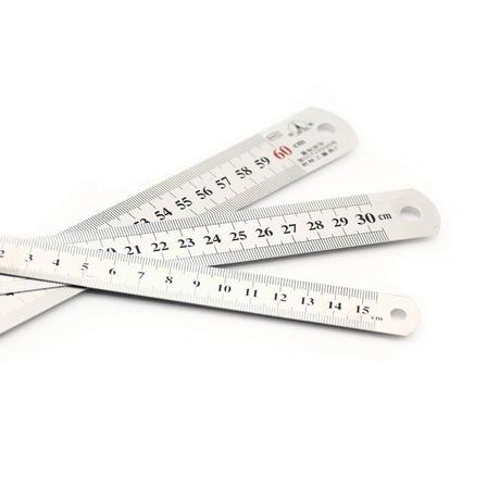
Straight ruler and set square
Rulers and set squares are basic measuring and marking tools for wooden sailboat model making. They are mainly used for measuring dimensions, drawing straight lines, calibrating right angles, and positioning angles for various components. They are essential measuring tools for ensuring a neat structure and symmetrical dimensions in ship models.
---
I. Stainless Steel Ruler
For ship model making, preferentially use a thickened stainless steel ruler. Compared with ordinary plastic rulers, its blade is straight and not easily deformed, and its sharp edges sit flush against the wood, providing higher marking accuracy. It is the main tool for cutting stock and positioning.
Specifications and Purchasing Tips
- Keeping two on hand covers most scenarios: a **15 cm portable model** is suitable for precise measurement of small components such as railings and rigging mounts; a **30 cm general-purpose model** is suitable for large wooden parts such as hulls, decks, and keels.
- For large ship models at 1:30 scale or larger, add a 60 cm long ruler.
- Prefer models with dual-sided graduations and a minimum graduation of 0.5 mm; a ruler with beveled edges sits more closely against the material, making markings more accurate without deviation.
Core Uses in Ship Model Making
1. When cutting hull planking and deck strips, use it with a scribing needle to draw straight lines, replacing pencils to reduce errors caused by line width
2. Measure frame spacing and mast section lengths to ensure the left and right structures of the hull are symmetrical
3. Hold it against the hull edge to check the overall straightness and smoothness of the hull
4. Use it as a reference straightedge for the set square to ensure vertical and diagonal lines are straight and do not shift
---
II. Transparent Set Square
Set squares are core tools for right-angle calibration and angle marking in ship modeling. Prefer high-clarity acrylic material, which allows clear observation of the lines on the wood underneath and ensures accurate positioning.
Specifications and Purchasing Tips
Two types of set squares are commonly used in ship modeling; it is recommended to have a complete set (two pieces) to cover all scenarios:
1. Isosceles right set square (45°/45°/90°): the most frequently used, for drawing 90° vertical lines and 45° bevel cuts.
2. 30°/60° right set square: for drawing special-angle lines for diagonal braces, gunport frames, decorative components, etc.
- Choose a small-to-medium model with a side length of 10–15 cm; an overly large set square is inconvenient to operate on small components.
- The key requirement is that the right-angle accuracy meets the standard, and the edges are straight and free of burrs, to avoid deviations during calibration.
Core Uses in Ship Model Making
1. When installing frames, hold it against both the keel and the frame to check 90° perpendicularity and prevent the entire hull from skewing
2. When dividing the deck into compartments and positioning gunports, use it with a ruler to draw perpendicular dividing lines and ensure a neat layout
3. When cutting diagonal supports and belaying posts, use the set square directly to draw standard bevels without an additional protractor
---
Use and Maintenance Tips
1. For fine marking, use a modeling scribing needle first; pencil lines are wider and easily cause errors of 0.2–0.5 mm.
2. Avoid dropping, striking, or applying heavy pressure to prevent edge deformation and loss of right-angle accuracy; during long-term use, periodically check accuracy with a standard right-angle reference.
3. When cutting wood, the ruler can serve as a guide straightedge; use it with a utility knife to ensure straight and smooth cuts.
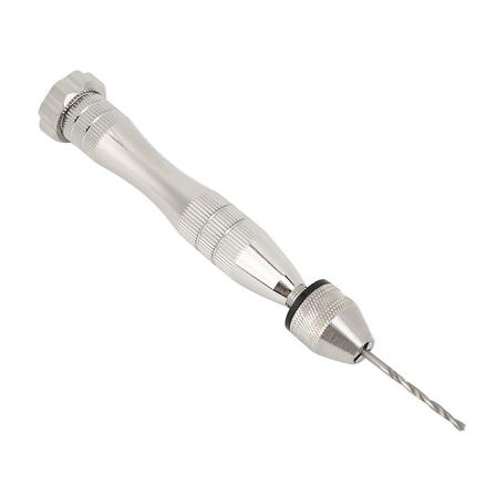
手工钻
# Hand Twist Drill (Model Hand Drill / Pin Vise)
The hand twist drill, also commonly called a hand drill or pin vise, is a standard fine drilling tool for wooden sailboat model making. It uses manual twisting to drive the drill bit for cutting, allows free disassembly and replacement of micro drill bits of different specifications, and is specially used for small-size precision drilling operations such as rigging holes, railing stanchion positioning, and component pin holes.
---
## Overall Appearance and Structure
Common model-specific hand twist drills have an all-metal pen-style shape and are compact enough to be held and operated with one hand, meeting the fine work requirements of ship model making.
- Locking chuck: The front end is a three-jaw chuck that can be loosened or tightened by rotation. The common clamping range is 0.3–3.2 mm and is compatible with all required drill bit sizes of 0.6, 0.7, 0.8, 1.0, and 2.0 mm.
- Non-slip handle: The shank has a knurled texture to increase friction, making it easy to apply finger force and turn at a steady speed.
- Tail end cap: The flat design can rest against the palm, making drilling more stable and less prone to wobbling or hand tremor.
---
Drill Bit Clamping Effect
To replace the drill bit, simply rotate the chuck locking ring. For extra-fine drill bits such as 0.6–0.8 mm, it is recommended to expose only 3–5 mm of the flute; exposing too much greatly increases the risk of breakage.
---
Matching Drill Bit Set Reference
Common micro twist drill bits for ship models can be used directly with the hand twist drill, covering all scenario requirements from fine rigging holes to mast fixing holes.
---
Core Advantages in Ship Model Applications
1. Protects fine drill bits: Manual speed is fully controllable and will not snap fine drill bits as easily as high-speed rotary tools, making it a reliable choice for drilling rigging holes in ship models.
2. High drilling accuracy: Feed force and drilling depth can be precisely controlled, so when drilling thin decks and fine hulls, it is less likely to deviate or drill through out of position.
3. Highly adaptable: It covers all micro straight-shank drill bits in the 0.4–3.0 mm range, and one set of tools can meet all small-hole requirements for ship models.
Key Points for Drilling in Ship Model Making
1. Before drilling, use a locating pin to make a small dimple on the wood surface to prevent the drill bit from slipping and wandering at the start.
2. Keep the drill bit perpendicular to the wood surface, press lightly and rotate at a uniform speed until you feel it cutting; do not force it with brute strength.
3. When drilling 1–2 mm thin decks/hull planking, place a piece of scrap wood behind the workpiece to avoid tear-out and splintering at the exit.
4. When drilling hardwoods (padauk, beech), slow down the pace and periodically withdraw the drill bit to clear wood chips to prevent clogging.
Purchasing Advice
Prefer all-metal precision hand twist drills, which offer better concentricity. Fine drill bits of 0.6, 0.7, and 0.8 mm are high-frequency wear parts, so it is recommended to buy 2–3 spare bits together with the hand twist drill.
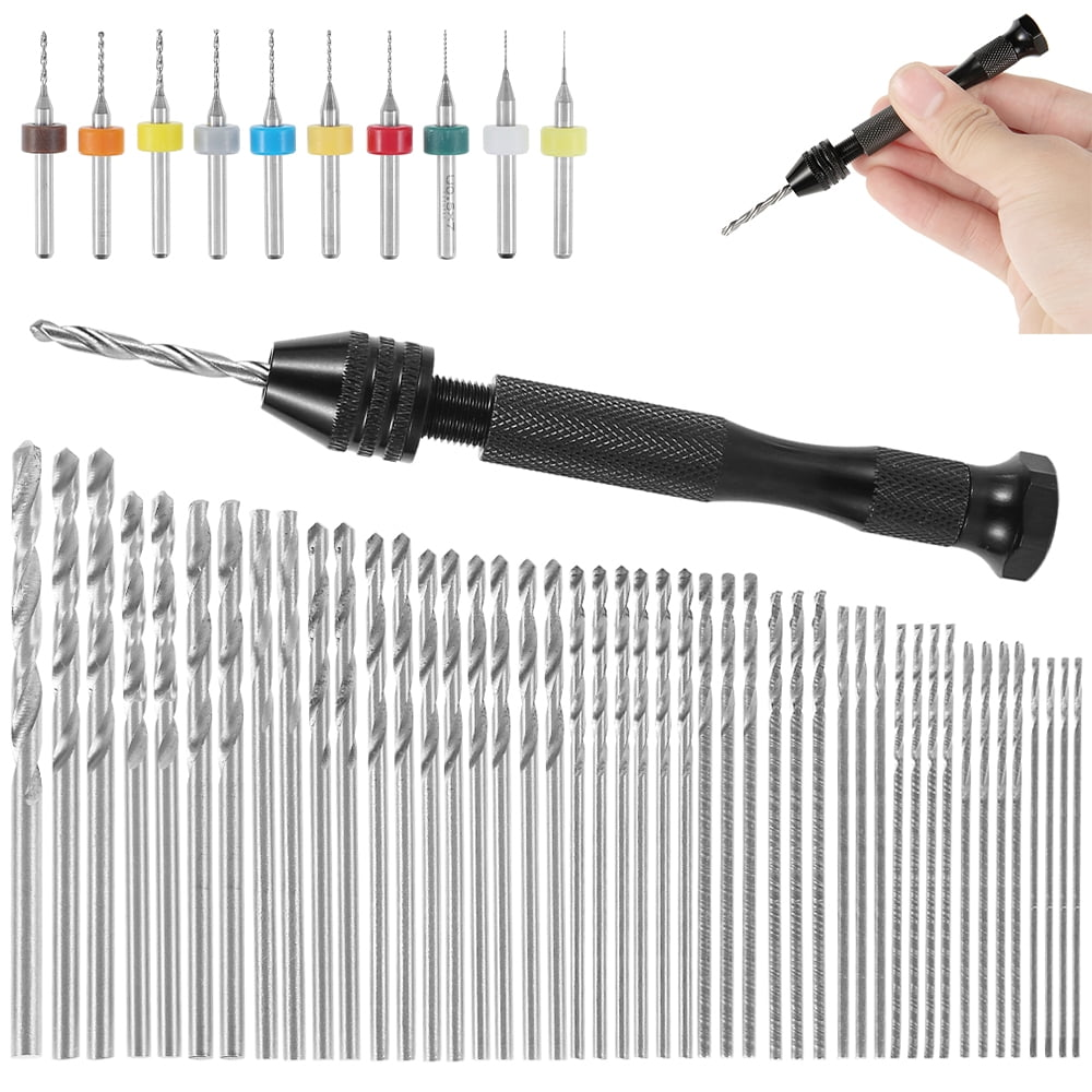
Drill bit
**Miniature HSS (high-speed steel) straight-shank twist drill bits (short-flute model-specific type preferred)**, preferably paired with a **precision pin vise**; direct use in a high-speed rotary tool is not recommended, as fine drill bits break very easily
Material: ordinary 6542 HSS is sufficient for ship models; tungsten carbide is more wear-resistant but extremely brittle—it breaks if slightly off-angle, so beginners should choose with caution
✅ Main specifications + uses
1. 0.6 mm: extra-fine rigging holes, threading holes for fine cotton/nylon thread, miniature railings, rope holes in small pulleys (fine thread ≤0.4 mm)
2. 0.7 mm: fine rigging, shrouds, small shrouds; the most commonly used size for ship model rigging
3. 0.8 mm: mainstream rigging hole! Standard for most 1:50–1:100 ancient sailing ships, for 0.5–0.6 mm cotton cord, positioning holes for bamboo/brass railing wire
4. 1.0 mm: thick rigging, sail control lines, bamboo post columns, mast seat positioning, cannon barrel retaining pins, small deck supports
5. 2.0 mm: thick bamboo rods, mast root mounting holes, large dowel pins, cannon carriage brackets, through-holes in thick wooden ribs/frames
✅ Suggested additions to complete a set (commonly kept by experienced ship modelers, filling in gaps, one-step solution)
On top of the 5 bits, add these sizes to cover almost all scenarios:
0.4, 0.5, 0.9, 1.2, 1.5 mm
Complete full set: 0.4, 0.5, 0.6, 0.7, 0.8, 0.9, 1.0, 1.2, 1.5, 2.0
- 0.4/0.5: ultra-small scale (1:100 and above) extra-fine rigging
- 0.9: between 0.8 and 1.0; specified hole diameter in many kit instructions
- 1.2: thick bamboo wire, thick brass posts
- 1.5: masts, thick supports, positioning of large components
📌 Key points for purchase/selection (pitfall avoidance)
1. Two shank diameter options
- Same-diameter shank: the finer the drill bit, the finer the shank → inexpensive, but 0.6 and 0.7 mm are not held securely and tend to deflect
- Uniform 1.0 mm shank (stepped shank): strongly recommended! For 0.4–0.9 mm cutting diameters, the rear end is a uniform 1.0 mm round shank; it is held securely in a hand drill and has good concentricity—the standard choice for model drill bits
2. Choose short-flute types, not lengthened micro drills: the longer a fine drill bit is, the more it wobbles and the more easily it breaks
3. Packaging: individually packed / with storage case preferred; fine drill bits are hard to find if lost
4. Spare-parts advice: 0.6, 0.7, and 0.8 mm break most easily; buy 2–3 spares of each of these three sizes at a time
🛠 Drilling companion operating guidelines (to go with your previous sanding process)
1. First mark with an awl / center punch to prevent the drill bit from slipping and wandering; especially important on softwood
2. Pin vise: **apply light pressure and rotate slowly; do not force it**; once you feel cutting, that is enough; if resistance increases, clear the chips immediately
3. Thin deck sheet (1–2 mm plywood): back it with scrap wood to prevent tear-out and edge splitting at the exit
4. Hardwoods (padauk, beech) wear drill bits faster than balsa; use slower rotation
5. Through-holes: reduce pressure when about to break through to avoid tearing the wood grain at the exit
## 📋 Quick selection card
- Fine-thread rigging: 0.4–0.7
- Standard rigging, railings: 0.8 (most frequently used)
- Small bamboo posts, thick rigging: 1.0 / 1.2
- Mast bases, large supports: 1.5 / 2.0
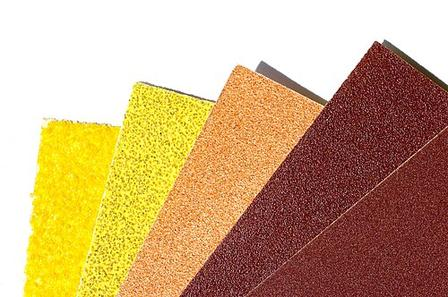
sandpaper
Sanding solid wood ship timber, laminated boards, wooden ribs, outer hull planking, and components; mainly dry sanding, with wet sanding allowed in fine stages; keep some of each grit coarseness on hand.
Principle: step up grit by grit, and strictly avoid large grit jumps; each grit must completely remove the scratches from the previous grit before switching to the next finer grit; sand along the wood grain to reduce tear-out and grain fuzzing.
Material notes: hardwoods such as beech, mahogany, padauk, and teak progress more slowly; softwoods such as balsa and pine tend to fuzz, so light wet sanding is recommended in later stages.
Basic sanding process (hull main body, ribs, deck, planking; the most commonly used standard version)
1. 80 grit: rough stock, burrs after cutting, laser-cut burn edges, excess glue marks, and leveling large height differences.
⚠️ Do not sand for too long; it is very easy to round over edges and corners or sand past the lines.
2. 120 grit: remove deep scratches from 80 grit, level the overall surface, correct height differences at joints and seams; most coarse defects are addressed by this point.
3. 240 grit: the core transition grit and the most important grade in model sanding; eliminate 120-grit scratches, and the wood surface becomes finer; softwoods tend to fuzz, so use light pressure at this step.
4. 400 grit: fine leveling, the standard base before applying primer / wood wax oil; after sanding, no obvious scratches are visible to the naked eye.
5. 600 grit: sand after the primer is fully dry (important! most ship models apply 1–2 coats of primer), sand off primer particles and runs/sags to obtain a fine primer base.
Advanced polishing route (for gloss clear coat, mirror-like finish, display-grade premium ship models)
Continue after the above 600 grit:
6. 800 grit: sand the first coat of clear coat
7. 1200 grit: sand the second coat of clear coat (can wet-sand with clean water, using a soft sanding block)
8. 2000 grit: after multiple clear coats, fine wet sanding to eliminate swirl marks
9. 3000 grit: ultra-fine wet sanding, after which polishing compound can be applied
Note on 5000, 7000, and 10000 grit: not recommended for routine use on general ship models; only use them for ultimate mirror-finish collector pieces; completely unnecessary for ordinary aged/distressed or matte antique ship models.
📌 Simplified scheme by part (time-saving version, suitable for mass production / practice ship models)
- Ribs and internal structures that cannot be seen: 80 → 120 → 240 → stop; no need for further fine sanding, since the interior is not visible, saving time
- Deck, outer hull, exposed decorative parts (railing bases, gun ports, etc.): 80 → 120 → 240 → 400 → 600 (sufficient for matte wood texture and wood wax oil effect)
- Collector-grade gloss-finish display ship: complete the full sequence above up to 2000–3000 grit
⚠️ Key precautions for ship model sanding
1. Sanding blocks are essential: use a hard sanding block for flat surfaces (outer hull planking, deck), and a soft sponge sanding block for curved surfaces and rounded bow/stern; holding sandpaper directly will definitely produce wavy surfaces.
2. Softwood (balsa) caution: after 240 grit, dry sand as much as possible; heavy wet sanding can easily raise wood fibers and cause fuzz/whiskers; if fuzzing occurs, lightly spray a coat of sealer primer and sand again.
3. Glue spots: 502 cyanoacrylate and wood glue lumps are very hard; remove them first with low grit (80/120), as fine sandpaper cannot cut through glue spots.
4. Sequence prohibition: never jump directly from 120 grit to 400 grit; scratches from the previous grit will remain buried, and after clear coating they will all become visible.
5. Aged/antique-style ancient sailing ships: stop sanding at 400 grit; do not go above 800 grit; retain a little wood grain texture—too smooth actually looks unrealistic.
🧾 Quick sequence summary card (easy to save)
Practice / matte wood wax oil version: 80# →120# →240# →400# →600#
Gloss clear-coat collector version: 80# →120# →240# →400# →600# →800# →1200# →2000# →3000#
Internal hidden components: 80# →120# →240#
Eclipse 模型胶水
快速蒸发型胶水,用于塑料模型部件粘合
郡士喷笔 PS290
0.2mm 精密喷笔,适合精细喷漆