Precision peach-jaw pliers
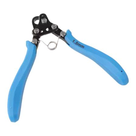
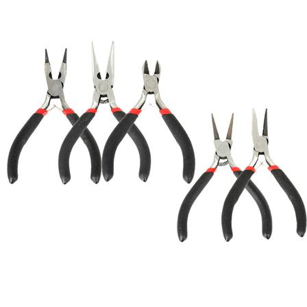
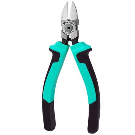
Peach-mouth pliers, also commonly called diagonal cutters, sprue cutters, or side cutters, are a dedicated cutting tool for machining metal components and hard materials in wooden sailing ship models. They are mainly used to cut thin metal wire, sprue burrs on metal parts, hard plastic fittings, and other relatively hard materials. With strong cutting force and clean, flat cuts, they can handle the cutting needs of slightly thicker and harder metal parts that the side-cutting jaws of needle-nose pliers cannot, making them an essential tool during the metal fittings fabrication stage.
Detailed Explanation of the Two Specifications and Their Uses in Ship Modeling
1. Standard Double-Blade Version (General-Purpose Main Cutting)
The jaws have a symmetrical double-blade structure, providing high cutting force and strong durability; it is the main configuration for daily rough cutting work.
- Core uses: cutting 0.5~1.5mm copper wire, iron wire, and copper rods; trimming excess length from 9-shaped pins and copper dowel pins; trimming sprue burrs on metal castings; and cutting off excess material edges on hard plastic fittings.
- Operating points: When cutting, apply force at the base of the cutting edge for more stable force and a cleaner cut; do not use the tip of the edge to cut thick, hard wire, to avoid chipping the edge tip.
2. Thin-Blade Precision Version (Fine Flush Cutting)
Single-bevel edge with an ultra-thin cutting edge; minimal compression deformation during cutting, with flat cuts and almost no burrs, suitable for fine cutting of visible appearance parts.
- Core uses: fine cutting of bright copper wire and thin metal railing wire; trimming excess length from exposed metal parts to ensure flat cuts without secondary grinding; also suitable for handling small connecting tabs on laser-cut sheet parts.
- Operating points: Use only for fine cutting of soft metals and plastics; do not cut high-hardness steel wire to avoid chipping the thin blade.
Core Application Scenarios in Ship Modeling
1. Cutting copper wire and copper rods to length: When making railings, 9-shaped pins, and bollards, cut the wire accurately to size.
2. Trimming and shaping metal parts: Trim sprue, burrs, and excess length from copper nails, copper pins, and metal pulley mounts.
3. Cutting hard fittings to size: Cut fittings made of hard plastics, Bakelite, and other relatively hard materials.
4. Reworking waste parts: Cut off excess metal connectors and correct misaligned metal components.
Usage and Maintenance Precautions
1. Material restrictions: The standard version is only suitable for soft metals such as copper and aluminum and for plastics. Do not cut high-strength steel wire or hard steel bars to avoid chipping and deformation of the cutting edge.
2. Cutting edge guidelines: Whenever possible, use the middle and rear sections of the cutting edge for cutting; do not use the tip to cut thick, hard materials with great force, to prevent tip chipping.
3. Prohibited uses: Do not use as pliers to grip heavy objects, and do not use as a pry bar, to avoid jaw misalignment and inaccurate blade engagement.
4. Daily maintenance: After use, wipe off metal chips and glue residue from the cutting edge; apply a small amount of oil to the pivot to prevent rust and ensure smooth opening and closing.
Mini carving knife
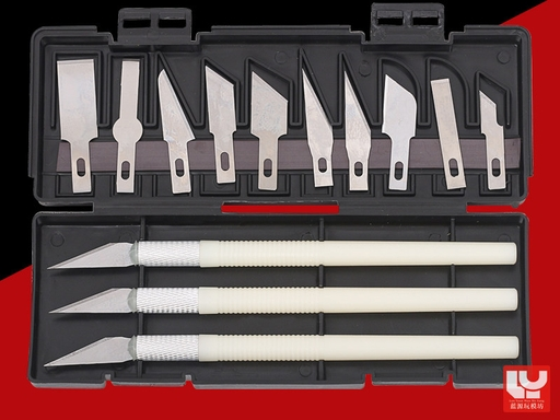
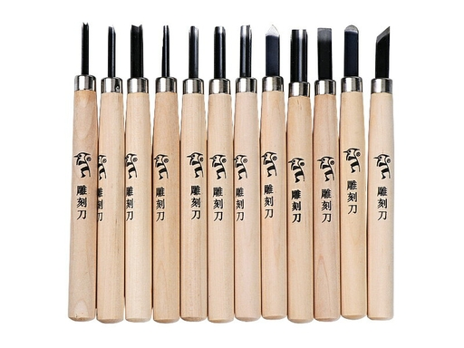
This is a cutting tool specially used in wooden sailing ship model making to remove excess wood. It lies between rough cross-cutting with a hand saw and fine sanding with sandpaper, and can perform thin wood cutting, edge and corner shaping, notch trimming, groove machining, detail carving, and other operations. It offers higher precision than a saw and faster stock removal than sandpaper, making it an essential tool for frame finishing and fitting part shaping.
Detailed Explanation of Each Blade Type and Corresponding Uses in Ship Modeling
1. Flat chisel (large-area surface stock removal)
The cutting edge is straight and regular, with a large cutting contact area and the highest stock removal efficiency.
- Core uses: Quickly level rough sawn cross-sections of square timber, level the bottom surfaces of joint notches between the keel and ribs, and remove large areas of excess wood; it is the main tool in the rough shaping stage.
- Suitable scenarios: Rough shaping of square timber, leveling of large notches, and removal of excess on thick wood.
2. Skew chisel (general-purpose edge-trimming workhorse)
The cutting edge is angled, and the tip is sharp and flexible, balancing stock removal efficiency and precision; it is the most frequently used general-purpose type.
- Core uses: Trim component edges and corners, machine angled notches, shave cured glue marks in joints, and finely adjust part dimensions.
- Suitable scenarios: Rib side edge shaping, fitting part edge trimming, and fine machining of angled components.
3. Gouge (dedicated to curved/concave groove machining)
The cutting edge is arc-shaped, specifically for machining curved surfaces and arc-shaped grooves.
- Core uses: Dig semicircular slots, trim the curved contours of the bow and stern, machine mast mounting grooves, and shape the outer profiles of cylindrical parts.
- Suitable scenarios: Curved decorative parts, semicircular notches, and cylindrical component shaping.
4. V-parting tool (fine-line/V-groove carving)
The cutting edge is V-shaped triangular, specifically for engraving lines and machining narrow grooves.
- Core uses: Carve simulated seam lines for hull plank joints, machine narrow V-shaped grooves, carve decorative details, and trim excess wood in internal corner dead areas.
- Suitable scenarios: Simulated wood grain engraved lines, narrow grooves on gunport frames, and decorative carving detail machining.
5. Pointed chisel (fine dead-corner shaping)
The tip is sharp and slender, allowing it to reach into narrow gaps for work.
- Core uses: Clean small notch dead corners, shape the contours of miniature parts, and remove excess glue marks and wood chips from gaps.
- Suitable scenarios: Shaping miniature fitting parts and fine trimming of narrow gaps.
Quick Selection Guide by Part
1. Keel, rib notches, hull trimming; core tools: flat chisel, skew chisel; machining stage: rough shaping after sawing.
2. Curved contours of bow and stern; core tools: gouge, skew chisel; machining stage: fine contour shaping.
3. Simulated wood grain and decorative engraved lines on the hull; core tool: V-parting tool; machining stage: appearance detail machining.
4. Edge and corner shaping of small fitting parts; core tools: skew chisel, pointed chisel; machining stage: fine trimming before assembly.
5. Groove and semicircular slot machining; core tool: gouge; machining stage: fine structural machining.
Usage and Maintenance Precautions
1. Stock removal principle: Follow the principle of small amounts and multiple passes, removing the allowance layer by layer. Never cut too deep in one pass to avoid wood splitting and over-cutting.
2. Cutting direction: Cut along the wood grain as much as possible; cutting against the grain can easily cause wood fibers to fuzz and edges to chip.
3. Safety rules: The blade is sharp. During operation, point the blade away from yourself to prevent slipping and cuts. Wearing safety gloves is recommended; put on the protective cap when not in use.
4. Dedicated tool for dedicated use: Use only on soft materials such as wood and soft plastic. Do not cut metal or hard cardboard to avoid rapid edge wear and chipping.
5. Cutting edge maintenance: When the blade becomes dull, hone it sharp with a fine oilstone along the cutting edge angle; a dull blade requires more effort to cut and slips easily, making operating mistakes more likely.
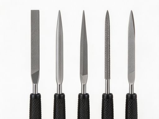
File
Files are the core shaping tools that bridge rough saw cutting and fine sandpaper sanding. They mainly solve problems that sandpaper struggles to handle efficiently, such as rough and uneven kerfs after sawing, insufficient precision of joint notches, shaping of irregular contours, and edge trimming and deburring of micro-hole inner walls. Through different tooth patterns, they adapt to various configurations such as flat surfaces, curved surfaces, internal corners, and round holes. They are essential tools in the frame finishing and component shaping stages.
---
Detailed Explanation of File Types and Corresponding Uses in Ship Modeling
1. Flat File (Mill File) · Mainstay for Flat-Surface Shaping
The file body is flat, with cutting teeth on both faces, making it the most frequently used basic model.
- Core uses: leveling sawn end faces of wood strips, trimming joint notches on keels and frames, leveling the side edges of deck planks, and correcting large-area flatness deviations; after sawing, use a flat file first to quickly level the coarse allowance, then transition to sandpaper sanding.
- Selection advice: choose one medium-cut and one fine-cut file each; coarse cut removes stock, fine cut smooths the surface.
2. Half-Round File · for Curved Surfaces/Arcs
One face is flat and the other is rounded, handling both flat and curved work.
- Core uses: shaping the curved contours of the bow and stern, sanding mast tapers and round components, trimming curved edges of frames, and cutting semicircular grooves; the curved face conforms to component curves, and shaping efficiency is much higher than with sandpaper.
- Selection advice: prefer a medium-width half-round file, suitable for most curved components.
3. Triangular File · for Internal Corners/Slots
The cross-section is triangular, with cutting teeth on all three edges, specifically for included angles and narrow slots.
- Core uses: trimming the internal corners of frame slots, cutting V-shaped notches, straightening and trimming the inner walls of narrow slits, and cleaning excess glue marks and wood dust from dead corners at joints; it can perform precision correction of right-angle joints and handle areas that flat files cannot reach.
4. Round File · for Round Holes/Curved Slots
The file body is cylindrical, with cutting teeth all around, suitable for round holes and curved slots.
- Core uses: enlarging rigging hole diameters, trimming burrs on the inner walls of drilled holes, making round pin holes, and refining curved grooves; when a hand drill leaves holes too small or inner walls not smooth, use a round file for fine hole enlargement and edge trimming.
- Selection advice: keep 1.0 mm and 2.0 mm diameters on hand, matching common hole diameters in ship modeling.
5. Knife File (Supplementary) · for Narrow Gaps/Fine Edge Trimming
The cutting edge is narrow and thin like a blade, suitable for finishing extremely narrow gaps.
- Core uses: trimming narrow gun-port slots, slotting thin wood strips, and trimming fine grooves on railing bases; for fine shaping in ultra-narrow areas, it is an advanced supplementary item and not essential for beginner projects.
---
Processing Sequence by File Cut Coarseness
File cut coarseness corresponds to different processing stages and connects logically with sanding, following the “coarse to fine” principle:
1. Coarse-cut file: quickly remove large stock after sawing and correct large deviations, leaving 0.1–0.2 mm finishing allowance.
2. Medium-cut file: the main shaping operation, leveling surfaces and correcting contours to achieve dimensional accuracy close to the finished part.
3. Fine-cut file: fine-finish and smooth surfaces, remove coarse-file scratches, and provide a transition to subsequent sandpaper sanding.
> After shaping wooden components, sand finely in the sequence 240# → 400# → 600# to obtain a flat and smooth surface.
---
Quick Reference for File Selection by Part
1. Keel, frame notches, and end faces; core files: flat file, triangular file; cut selection: coarse cut → medium cut.
2. Curved contours of bow and stern; core files: half-round file; cut selection: medium cut → fine cut.
3. Masts and cylindrical parts; core files: half-round file, round file; cut selection: medium cut → fine cut.
4. Edge trimming and hole enlargement of rigging holes and pin holes; core files: round file; cut selection: fine cut.
5. Gun ports, narrow slots, and internal corners; core files: triangular file, knife file; cut selection: medium cut → fine cut.
6. Fine finishing of small fitting parts; core files: full set of fine needle files; cut selection: fine cut.
---
Usage and Maintenance Precautions
1. Filing direction: push and apply pressure along the wood grain; lift the file off the wood on the return stroke to avoid filing against the grain, which can cause wood fibers to fuzz and edges to tear out.
2. Force principle: advance with light pressure and steady speed, relying on the file teeth to cut naturally; excessive force can cause file teeth to chip off and wood to crack.
3. Timely chip removal: wood dust packed between file teeth reduces cutting efficiency; clean with a wire brush along the tooth direction; do not blow chips off with your mouth.
4. Dedicated use: wood files are only for wood and soft plastics; do not file metal parts directly, to avoid rapid tooth wear and chipping; when filing brass pins or metal parts, keep a separate metal-specific file.
5. Storage protection: file teeth are relatively brittle; avoid mixing and bumping with hard objects such as wrenches and pliers to prevent tooth tips from chipping.
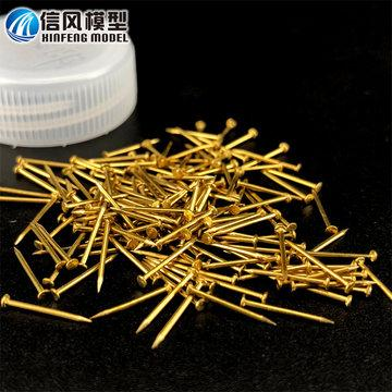
Miniature copper nail category
Copper nail categories for ship models are core accessories for structural reinforcement and simulated fittings of wooden sailing ship models. Used together with mini hammers, pin vise drills, and tweezers, they serve both structural fastening and appearance simulation. The complete system covers three major categories—structural fastening, exposed decoration, and dedicated fittings—fully covering the fabrication needs of all scenarios from the main frame to detail decoration.
---
I. Composition of the Complete Nail Set + Supporting Tool Collection
6 nail types + 4 supporting installation tools, corresponding to all modeling scenarios. The complete list is as follows:
> Supporting tools: mini double-head hammer (nylon + brass double heads), precision pin vise drill, straight-tip stainless steel tweezers, tungsten carbide locating scribe.
> Nail types: copper cylindrical dowel pins, round-head brass nails, countersunk-head brass nails, wooden dowel pins, simulated decorative rivets, brass figure-nine nails.
---
II. Full Analysis of Core Nail Types
1. Copper cylindrical dowel pins (mainstay for hidden structural positioning)
Headless pure cylindrical copper rods rely on an interference fit with the wood for fastening. After installation, they are completely hidden with no exposed marks, offering high positioning accuracy and good structural strength.
- Core uses: keel-to-rib joining and positioning, internal fixing of mast bases, movable pivot shafts of gun carriages, hidden component joining and reinforcement.
- Common specifications: 0.6 mm / 0.8 mm / 1.0 mm / 1.2 mm / 1.5 mm / 2.0 mm.
- Matching drill bits: pilot hole diameter equal to or 0.05 mm smaller than the pin diameter to achieve an interference fit.
2. Round-head brass nails (general fastening + exposed simulation)
Semicircular head, brass material is rustproof and corrosion-resistant, with moderate hardness and not easy to bend. They balance structural fastening and appearance simulation and are the most frequently used general-purpose type.
- Core uses: exposed fastening of hull planking, bulwarks, rubbing strakes, and fittings; the nail heads directly serve as simulated details.
- Common specifications: 0.5 mm / 0.6 mm / 0.7 mm / 0.8 mm / 1.0 mm / 1.2 mm.
- Matching drill bits: pilot hole diameter = nail diameter − 0.1 mm, ensuring holding power while avoiding splitting the wood.
3. Countersunk-head brass nails (dedicated for flush surface fastening)
Tapered countersunk head design; after driving in, they are flush with the wood surface with no protrusion and do not affect subsequent sanding and painting processes.
- Core uses: deck planking installation, exposed hull nails, fastening of flat decorative parts, and exposed surfaces requiring extreme flushness.
- Common specifications: 0.6 mm / 0.7 mm / 0.8 mm / 1.0 mm.
- Matching drill bits: pilot hole diameter = nail diameter − 0.1 mm. For large-scale models, a chamfer bit can be used to countersink the hole.
4. Wooden dowel pins (fully hidden, traceless reinforcement)
Solid wood round rods of the same material as the model; after bonding, they blend into the base wood with no color difference and no metallic foreign-body feel.
- Core uses: hidden positioning of internal frames, reinforcement of deck strip joints, and appearance structures where exposed metal is not allowed.
- Common specifications: 0.8 mm / 1.0 mm / 1.2 mm / 1.5 mm.
- Matching drill bits: pilot hole diameter 0.1–0.2 mm smaller than the dowel diameter; bonding with wood glue gives higher strength.
5. Simulated decorative rivets (pure appearance detail type)
Extremely fine flat-bottomed copper nails/copper beads with no actual structural load-bearing; used only to reproduce the visual details of rivets on real ships.
- Core uses: cannon hoop rivets, ship nameplate decoration, simulation of metal fittings; in small-scale models they replace real nails to avoid splitting thin plates.
- Common specifications: 0.3 mm / 0.4 mm / 0.5 mm.
- Installation method: shallow hole + cyanoacrylate adhesive; no need to drive deeply.
#6. Figure-nine nails (dedicated nails for mooring fittings)
Also called hook nails or mooring nails; made of brass and shaped like a "9" as a whole, with one end being a straight shank that can be driven in for fastening and the other end a curved hook for hanging ropes and mooring lines. They are an iconic fitting of ancient sailing ship rigging.
- Core uses: simulate mooring bitts and fairlead hooks on real ships; used for rope attachment points on decks and bulwarks, fixing the ends of anchor chains and shrouds, greatly improving the realism of fittings.
- Common specifications:
- Large-scale models (1:20–1:48): shank 0.8–1.2 mm, hook inner diameter 2–4 mm.
- Medium-scale models (1:50–1:80): shank 0.6–0.8 mm, hook inner diameter 1.5–2.5 mm.
- Small-scale models (1:96–1:150): shank 0.4–0.5 mm, hook inner diameter 1–1.5 mm.
- Key installation points: drill corresponding pilot holes in advance, apply a small amount of cyanoacrylate adhesive to the shank and drive it in, orient all hooks toward the outboard side, and arrange them evenly along the bulwarks and deck edges.
---
III. Specification Selection Table by Model Scale
| 1:20–1:48 Large-scale large ship models | Structural pins: 1.0–2.0 mm | Exposed fastening nails: 0.8–1.2 mm | Figure-nine nail shank: 0.8–1.2 mm | Matching drill bit specifications: 0.8 / 1.0 / 1.8 mm | Typical applications: main frame, thick hull planking, mast base, large gun carriage |。
| 1:50–1:80 | Medium-scale mainstream ship models | Structural pins: 0.7–1.2 mm | Exposed fastening nails: 0.7–0.8 mm | 0.6–0.8 mm | Matching drill bit specifications: 0.6 / 0.7 / 1.0 mm | Typical applications: hull planking, deck nails, bulwarks, rib positioning, general fittings |。
| 1:96–1:150 | Small-scale fine ship models | Structural pins: 0.4–0.8 mm | Exposed fastening nails: 0.4–0.6 mm | Figure-nine nail shank: 0.4–0.5 mm | Matching drill bit specifications: 0.3 / 0.5 / 0.7 mm | Typical applications: decorative rivets, fine railings, miniature gun parts, small mooring points |。
---
## IV. Detailed Uses and Specification Selection by Part
1. Main frame (keel/ribs/beams)
- Core function: structural positioning + deformation-resistant reinforcement, compensating for the load-bearing shortcomings of purely glue-bonded joints.
- Nail types: copper cylindrical dowel pins / wooden dowel pins (fully hidden, not exposed).
- Corresponding specifications: large scale 1.5–2.0 mm; medium scale 1.0–1.2 mm; small scale 0.6–0.8 mm.
- Key operation points: the dowel pins pass through the keel and ribs; apply wood glue to both ends and drive them in; after curing, sand flush so they are completely hidden without marks.
2. Hull planking
- Core function: assist glue in fixing hull planks, prevent debonding due to thermal expansion and contraction; reproduce the simulated effect of exposed nails on real ship planking.
- Nail types: round-head brass nails / countersunk-head brass nails (choose countersunk for a flush finish).
- Corresponding specifications: large scale 1.0–1.2 mm; medium scale 0.8 mm; small scale 0.5–0.6 mm (or paint dots to simulate fake nails).
- Key operation points: distribute evenly along the plank seams; when hammering thin planks, the back must be backed with scrap wood to prevent splitting.
3. Deck system
- Core function: fix deck planking strips (for the second deck layer, second-layer hull planking strips can be used), simulating the real deck nail installation pattern.
- Nail types: countersunk-head brass nails (flush with the deck after installation); decorative rivets for small scales.
- Corresponding specifications: large scale 0.8–1.0 mm; medium scale 0.6–0.8 mm; small scale 0.4–0.5 mm.
- Key operation points: for large scales, pre-countersink with a chamfer; position nails symmetrically along both sides of the deck strips for higher realism.
4. Bulwarks and mooring fittings
- Core function: fix bulwark planks and rubbing strakes, and reproduce the details of mooring attachment points.
- Nail types: round-head brass nails (structural fastening) + figure-nine nails (mooring attachment points).
- Corresponding specifications:
- Fastening nails: large scale 1.0–1.2 mm; medium scale 0.7–0.8 mm; small scale 0.5–0.6 mm.
- Figure-nine nails: large scale shank 0.8–1.2 mm; medium scale 0.6–0.8 mm; small scale 0.4–0.5 mm.
- Key operation points: the hooks of figure-nine nails face outboard and are evenly arranged; ropes hang naturally after being hooked, reproducing the real mooring effect.
5. Mast and rigging bases
- Core function: fix load-bearing components such as mast bases, pulley block seats, and shroud rings.
- Nail types: copper pins (internal positioning) + round-head copper nails (exposed fastening).
- Corresponding specifications: large scale 1.2–1.5 mm pins + 1.0 mm round-head nails; medium scale 0.8–1.0 mm pins + 0.8 mm round-head nails; small scale 0.6–0.8 mm pins + 0.6 mm round-head nails.
- Key operation points: the mast base is a load-bearing position; dual fixation with pins + glue is recommended to prevent loosening from rigging tension later.
6. Cannons and movable fittings
- Core function: gun carriage pivot shafts, anchor chain fixing, movable hatch hinges.
- Nail types: copper cylindrical dowel pins (as pivots) + miniature round-head nails (fixing gun carriages) + decorative rivets (simulating cannon hoops).
- Corresponding specifications: large scale 1.0–1.2 mm pins; medium scale 0.6–0.8 mm pins; small scale 0.4–0.5 mm pins.
- Key operation points: pivot pins need about 0.05 mm clearance to ensure smooth rotation without sticking.
7. Fine decorative parts (railings, ship nameplates)
- Core function: ultra-realistic fastening, replacing glue to avoid glue overflow contamination.
- Nail types: ultra-fine decorative rivets / 0.4–0.6 mm miniature round-head nails.
- Scope of application: only for large-scale collector-grade models; ordinary practice models can simply be bonded with cyanoacrylate adhesive.
---
V. Supporting Tools and Installation Operation Specifications
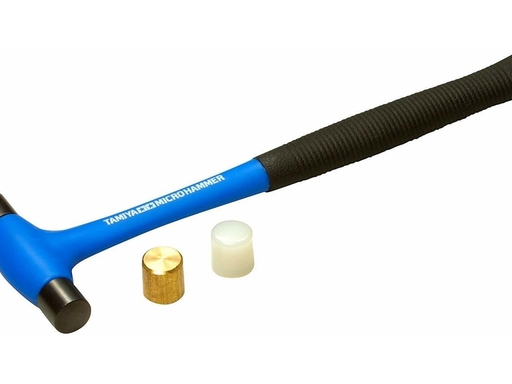
1. Mini double-head hammer: one end is a soft nylon head (for hammering wood surfaces, preventing dents and chipped edges), and the other is a brass head (for hammering nails, less likely to bend fine nails).
2. Precision pin vise drill: manually drill pilot holes of the corresponding size at low speed; small holes are precise without chipping, protecting thin wood.
3. Straight-tip tweezers: hold fine nails in alignment, preventing fingers from blocking the view and the nail shank from tilting.
4. Locating scribe: mark positions on the wood surface in advance to prevent the drill bit from slipping off.
Standard Installation Procedure
1. Positioning and marking: use a scribe to mark hole positions on the wood surface and make shallow dimples to prevent the drill bit from slipping.
2. Matching pilot hole: select the corresponding drill bit according to nail diameter, drill vertically with a pin vise drill; hole depth should be 0.5–1 mm deeper than the nail length to leave space for wood chips.
3. Holding nail in alignment: use tweezers to grip the nail shank and align it with the hole; tap 1–2 times to secure it before releasing.
4. Tapping into place: tap evenly and lightly with the brass hammer head; reduce force near the end to avoid damaging the wood surface.
5. Final reinforcement: exposed nails can be reinforced with a small dot of cyanoacrylate adhesive; hidden dowel pins bonded with wood glue have higher strength.
Key Pitfalls to Avoid
- Never hammer nails directly without drilling pilot holes; this can easily split thin wood sheets and cause splitting along the grain.
- When hammering thin wood or wood edges, the back and sides must be supported with scrap wood to prevent chipped edges.
- For small-scale thin plates, preferentially use the "fake-nail method": dip a needle tip in dark paint and dot the nail positions, completely avoiding the risk of splitting.